








Carrier Tape Design Guide: Pocket, Pitch & Tolerance Explained
Why Carrier Tape Design Matters in SMT Packaging
In SMT packaging, carrier tape is not a passive container—it is a functional part of the feeding system. Every pocket, pitch, and tolerance decision directly affects how reliably components advance, present, and release under automated pick-and-place conditions. When design is correct, feeding becomes predictable and stable. When design is flawed, even slightly, issues tend to surface downstream as mispicks, jams, component damage, or yield loss.
A common misconception is that carrier tape can be “drawn” by following standard dimensions. In reality, standard sizes only define nominal references, not whether a design will function at production speed. High-speed SMT lines amplify small design errors into system-level failures, especially when tolerances accumulate over hundreds or thousands of pockets.
This is why carrier tape should be treated as an engineered solution, not a packaging afterthought. Design decisions must be made with feeder behavior, automation speed, and process stability in mind—well before manufacturing begins.
Key Elements in Carrier Tape Design
Effective carrier tape design is built around three tightly linked elements: pocket design, pitch selection, and tolerance control. While these factors are often discussed separately, in practice they function as a single system. A design that appears correct in isolation can still fail once integrated into an SMT feeding environment.

Pocket design defines how the component is held, protected, and presented for pick-up. Pitch determines how that pocket is indexed and positioned relative to feeder movement. Tolerance control governs whether those two elements remain functionally aligned over the full tape length. Any imbalance between them introduces instability—either through inconsistent component position, poor release behavior, or cumulative feeding error.
A common design pitfall is optimizing one variable while assuming the others will “follow standard.” For example, a well-shaped pocket may perform poorly if the pitch does not match feeder indexing behavior, or if tolerance variation causes gradual misalignment. Conversely, a theoretically correct pitch can become a bottleneck if pocket geometry restricts component orientation or access.
From an engineering standpoint, carrier tape design should be approached as a coordinated system, not a checklist of dimensions. Decisions must be evaluated based on how they interact during continuous feeding, not just how they appear on a drawing.
Carrier Tape Pocket Design Considerations
Pocket design is the most component-specific part of carrier tape engineering. Unlike width or pitch, which are often constrained by feeder systems, pocket geometry must be tailored to the actual shape, mass distribution, and handling requirements of the component itself. A pocket that ignores component geometry may appear acceptable on paper but fail under real feeding conditions.
The first consideration is the relationship between pocket shape and component geometry. Components with asymmetrical bodies, exposed leads, or uneven mass require controlled orientation within the pocket. If the pocket allows rotation, tilt, or lateral movement, the pick-up position becomes inconsistent, increasing the risk of mispicks or placement errors.
Pocket depth introduces a second trade-off. Shallow pockets can improve pick-up accessibility but may reduce retention during transport and feeding. Deeper pockets improve stability but can interfere with vacuum access or cause delayed release. Effective design balances secure holding with predictable release behavior at speed.
Lead and terminal protection is another critical factor. Pocket walls must prevent contact or stress on sensitive leads during indexing and cover tape peel, without constraining the component so tightly that deformation or sticking occurs. This is particularly important for fine-pitch or fragile terminations.
Finally, pick-up accessibility must be considered early. Nozzle access, component exposure, and clearance above the component are design variables, not assumptions. A pocket that “fits” the component is not necessarily pickable in a high-speed SMT environment.
For components that fall outside standard pocket assumptions, custom pocket geometry is often required.
Pitch Selection in Carrier Tape Design
Pitch selection plays a critical role during the design stage because it defines how pockets advance and stop within the feeder. Unlike pocket geometry, which interacts directly with the component, pitch interacts primarily with the mechanical behavior of the SMT feeder. This makes pitch one of the most common—and least forgiving—system constraints in carrier tape design.
In practice, pitch determines how consistently each pocket aligns with the pick position after indexing. If pitch selection does not match feeder indexing behavior, even a well-designed pocket can arrive slightly early or late at the pick-up point. At low speeds this may be tolerated, but as placement rates increase, these deviations quickly translate into mispicks or nozzle compensation errors.
Pitch is also where small dimensional variations begin to accumulate. Each indexing step repeats hundreds or thousands of times across a reel. When pitch consistency is marginal, minor deviations add up along the tape length, creating gradual misalignment that is difficult to diagnose from a single-pocket measurement.
For this reason, pitch often becomes the system bottleneck rather than an isolated dimension. Designers may assume that choosing a “standard” pitch guarantees compatibility, but functional performance depends on how that pitch behaves across the entire feeding cycle, not just at nominal size.
Because pitch directly links carrier tape design to feeder mechanics, it deserves early attention in the design process—not after pocket geometry is finalized.
Tolerance Control and Accumulated Error in Carrier Tape Design
In carrier tape design, tolerance matters more than any single nominal dimension. While drawings often focus on target values, feeders respond to functional variation—how much dimensions can shift and still remain stable over continuous indexing. A design that meets nominal specifications can still fail if tolerance behavior is not controlled as a system.
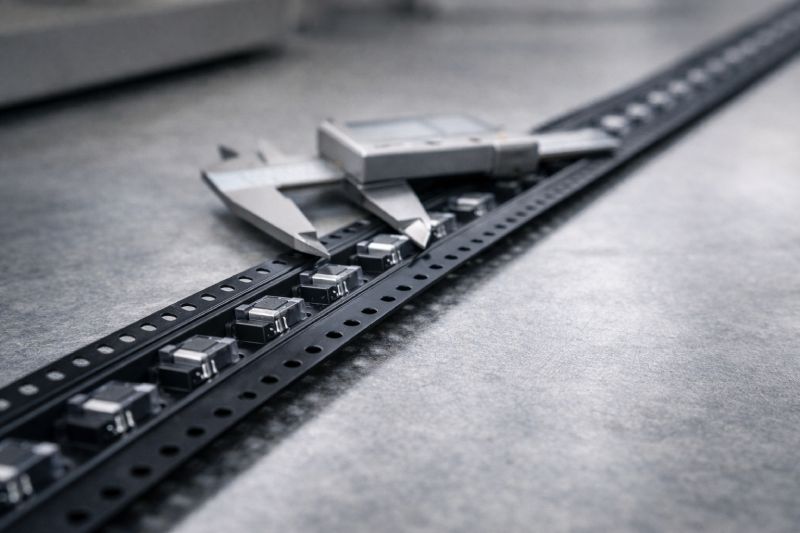
One critical distinction is between nominal dimension and functional tolerance. Nominal values describe intent; tolerances define reality. During feeding, the feeder does not “see” the nominal pitch or pocket position—it reacts to the actual position of each pocket as it arrives at the pick point. If variation exceeds what the feeder can absorb, instability follows.
Accumulated error is where tolerance becomes a system-level issue. Small deviations per pitch may appear insignificant when measured locally, but repeated over hundreds of pockets, they compound into visible misalignment. This often explains why feeding appears stable at the beginning of a reel but degrades over time without any obvious single defect.
Because of this, tolerance should never be treated as a secondary drawing note. It directly determines long-term feeding consistency, especially in high-speed SMT environments where correction windows are minimal. From an engineering perspective, controlling how variation accumulates is more important than tightening any one dimension in isolation.
Effective carrier tape design therefore evaluates tolerance as a continuous behavior across the tape, not as isolated pass/fail limits. This mindset shift—from “dimension accuracy” to “functional stability”—is essential for reliable SMT packaging.
How Material Choice Affects Carrier Tape Design
Material selection directly influences what is realistically achievable in carrier tape design. While pocket geometry, pitch, and tolerance define functional intent, material properties determine whether that intent can be formed, repeated, and controlled in production.
Different materials exhibit different forming behaviors. Stiffer materials may hold pocket geometry more consistently but limit how complex or deep a pocket can be embossed. More flexible materials allow greater forming freedom but may introduce elastic recovery, affecting dimensional stability after forming. These behaviors must be considered during design, not corrected later through tooling adjustments.
Material choice also affects tolerance control. Thickness variation, shrinkage characteristics, and thermal response all influence how consistently pitch and pocket position can be maintained over long tape lengths. A design that performs well in one material may show unacceptable variation when transferred to another, even if nominal dimensions remain unchanged.
Pocket complexity is another constraint imposed by material. Sharp corners, fine details, or thin supporting walls may be theoretically sound but impractical in certain plastics due to tearing, thinning, or inconsistent forming. In these cases, material limits dictate design simplification to preserve functional reliability.
Common Mistakes in Carrier Tape Design
Many carrier tape issues trace back to design assumptions rather than manufacturing defects. One of the most common mistakes is designing a pocket that “just fits” the component. While this may appear efficient, minimal clearance often leads to sticking, poor release, or stress on leads once real feeding dynamics are introduced.
Another frequent oversight is ignoring component orientation. Components that are allowed to rotate or tilt inside the pocket may still pass visual inspection, yet behave unpredictably under high-speed indexing. Orientation control must be designed into the pocket, not expected from the feeder or nozzle.
Designers also tend to focus on pitch as a standalone parameter while overlooking tolerance behavior. A nominally correct pitch can still cause feeding drift if accumulated variation is not controlled. In practice, tolerance consistency matters more than the target value itself.
Finally, many designs are created without considering actual SMT line speed. A carrier tape that works acceptably at low placement rates may fail as speeds increase. Designing for the intended production environment—not just for compliance—separates robust carrier tape design from trial-and-error solutions.
Design Validation Before Mass Production
Carrier tape design should always be validated as a process, not assumed correct based on drawings alone. Before mass production, prototype and sampling stages are essential to confirm that pocket geometry, pitch behavior, and tolerance performance translate into stable feeding under real conditions.
Initial prototypes allow engineers to observe component retention, orientation stability, and release behavior during cover tape peel and indexing. Issues identified at this stage are far easier to correct than after tooling and large-scale production are committed. Sampling across multiple short runs also helps reveal early signs of variation that may not appear in a single test strip.
Line testing is equally critical. Feeding performance must be evaluated on actual SMT equipment, at representative line speeds. This is where accumulated error, nozzle access limitations, or marginal tolerances typically become visible. A design that feeds smoothly in isolation may behave differently once integrated into a full production environment.
Iteration should be expected, not avoided. Design validation is an engineering feedback loop, and each adjustment improves functional stability. Clear drawing communication plays a key role in this process.
When Custom Carrier Tape Design Is Required
Standard carrier tape designs are suitable for many components, but there are clear situations where a custom approach becomes necessary. The first is when components fall outside common size or geometry assumptions. Irregular shapes, exposed leads, unusual mass distribution, or strict orientation requirements often exceed what standard pocket designs can reliably handle.
High-speed SMT lines are another trigger for custom design. As placement rates increase, the tolerance for variation decreases. Designs that are marginally acceptable at moderate speeds may become unstable when feeders index faster and correction windows narrow. In these cases, custom pocket geometry and tighter system-level control are required to maintain yield.
Custom design is also justified in yield-critical production. When components are high value, difficult to replace, or sensitive to handling damage, the cost of feeding instability quickly outweighs the effort of a tailored carrier tape solution. Here, design priorities shift from general compatibility to predictable, repeatable behavior.
In all of these scenarios, custom carrier tape design is not about deviation from standards, but about aligning pocket, pitch, and tolerance with real production demands.
Summary
Carrier tape design is fundamentally a system-level engineering task, not a drafting exercise. Pocket geometry, pitch selection, and tolerance control work together to determine whether components feed consistently under real SMT conditions. Treating any one of these elements in isolation increases the risk of instability, accumulated error, and yield loss—especially as automation speed increases.
A robust design starts by understanding how components behave in motion, how feeders index repeatedly, and how small variations compound over long tape lengths. Standard dimensions provide a reference, but functional performance depends on how well the design aligns with the actual production environment.
For engineers evaluating or refining a design, the next step is to apply these principles to a specific application—either by reviewing an existing tape or by validating a custom solution.



 Emial
Emial John Mr


