








Carrier Tape Pitch Explained: Definition, Measurement, and SMT Impact
Why Carrier Tape Pitch Matters in SMT Packaging
In SMT packaging, carrier tape pitch is not just a spacing value—it is a timing control parameter that directly governs how components arrive at the pick-up position. Every feeder indexes the tape in fixed increments. That indexing rhythm is defined by pitch, not by pocket size or component length.
When pitch is consistent, components advance smoothly, align correctly under the pick-and-place nozzle, and remain stable during high-speed operation. When pitch drifts—even slightly—the feeder’s indexing and the tape’s actual pocket positions fall out of sync. The result is familiar to any SMT engineer: mis-picks, rotated parts, skipped pockets, or tape jams that interrupt the line.
Because of this, pitch sits at the core of the tape & reel system alongside sprocket holes and feeder mechanics. It is one of the few parameters that directly affects placement stability across thousands of cycles, making it an engineering-critical variable rather than a simple dimensional detail.
What Is Carrier Tape Pitch?
Carrier tape pitch is defined as the center-to-center distance between two adjacent pockets along the tape’s feed direction.
This definition is used consistently in SMT engineering because it reflects how the feeder actually indexes the tape—not how large the pocket is, nor how long the component may be.
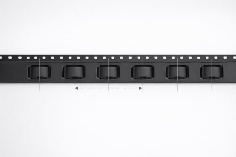
From a system perspective, pitch is tightly coupled with sprocket hole indexing. Each feeder advance corresponds to one pitch increment, ensuring that every pocket is positioned precisely under the pick-and-place nozzle at the correct moment. As long as the pitch is uniform, the mechanical indexing of the feeder and the physical position of the pockets remain synchronized.
It is important to clarify what pitch is not. Pitch is not pocket length, not pocket depth, and not a proxy for component size. Two carrier tapes can hold identical components yet use different pitches, depending on feeding rhythm and system requirements. Understanding this distinction is essential for accurate measurement and stable SMT operation.
Pitch vs Pocket Size vs Tape Width
Pitch, pocket size, and tape width are often discussed together, but they solve different engineering problems within the SMT feeding system. Confusing their roles is one of the most common sources of design and measurement errors.
Pocket size answers a containment question: whether the component fits securely, remains protected, and avoids movement or damage during transport. It is primarily about geometry and mechanical protection.
Tape width addresses compatibility: whether the carrier tape matches the feeder lane, guide rails, and cover tape format. A correct width ensures the tape can physically run through the feeder without lateral instability.
Pitch, by contrast, controls timing. It determines how each component advances into the pick position and whether that advance stays synchronized with feeder indexing.
These parameters do not operate independently. A well-designed carrier tape balances all three so that components are held securely, guided correctly, and delivered at a stable rhythm. Focusing on pocket size or width while neglecting pitch often leads to feeding instability, even when everything appears dimensionally correct.
Standard Carrier Tape Pitch According to EIA-481
In SMT packaging, carrier tape pitch is not defined arbitrarily. The industry relies on EIA-481 to establish a common reference framework that ensures tapes, feeders, and pick-and-place machines work together reliably across suppliers and regions.
EIA-481 was created to solve a practical problem: without standardized pitch values, feeder indexing would vary from tape to tape, making stable automation impossible at scale. By defining nominal pitch categories and their relationships to sprocket holes and tape geometry, the standard enables predictable feeding behavior regardless of component type or manufacturer.
Within this framework, pitch values are grouped into commonly adopted increments that align with feeder mechanics and indexing logic. These standard pitches form the backbone of tape & reel compatibility in modern SMT lines. While the standard allows controlled tolerances, the intent is clear—pitch must remain uniform enough to preserve synchronization between mechanical indexing and pocket position.
It is important to view EIA-481 as a system guideline rather than a checklist of numbers. Its role is to maintain feeding consistency and cross-platform interoperability, not to dictate design decisions in isolation.
How to Measure Carrier Tape Pitch Correctly
Measuring carrier tape pitch correctly requires an engineering approach, not a single quick measurement. Because pitch controls feeder indexing rhythm, small local deviations can accumulate into significant feeding problems if they are not identified properly.
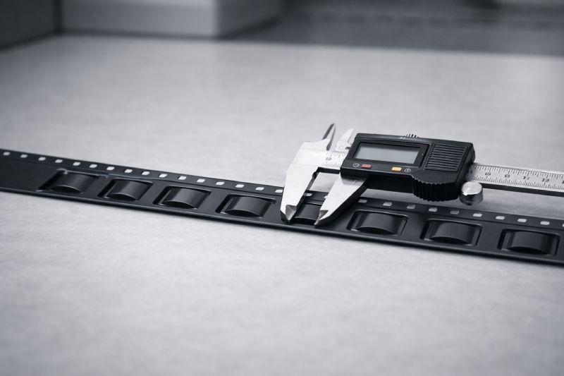
The first step is to identify the correct reference points. Pitch should always be measured center-to-center—either between adjacent pocket centers or between corresponding sprocket holes that define the feed index. Edge-to-edge measurements may look precise, but they do not represent how the feeder advances the tape.
Next, avoid measuring only one interval. A single pitch can appear accurate while masking gradual drift or forming errors. Instead, measure multiple consecutive pitches in a straight, undeformed section of tape, then divide by the number of intervals to obtain an average value. This method reduces the influence of local irregularities and reveals cumulative deviation.
Finally, inspect the tape condition before measuring. Distorted, stretched, or heat-affected sections can produce misleading results that do not reflect functional feeding behavior. Accurate pitch measurement is about understanding how the tape performs over repeated indexing cycles—not just confirming a nominal dimension.
This multi-interval approach is essential for evaluating real SMT feeding stability and avoiding downstream placement issues.
Common Mistakes in Carrier Tape Pitch Measurement
Most pitch measurement errors do not come from poor tools, but from misunderstanding what the measurement is meant to represent. One frequent mistake is measuring edge-to-edge instead of center-to-center. While edge references feel intuitive, they ignore how feeders index the tape and often produce values that look consistent but are functionally irrelevant.
Another common issue is measuring only a single pitch interval. Local forming accuracy can hide gradual drift across multiple pockets. A tape may pass a single-point check yet still cause cumulative misalignment after dozens of indexes, leading to skipped picks or jams during production.
Tape deformation is also often overlooked. Heat exposure, winding tension, or handling stress can subtly stretch or compress sections of tape. Measuring these areas without inspection can misrepresent the tape’s true feeding behavior.
Finally, pitch is sometimes confused with pocket length. Pocket geometry affects component fit, but it does not define indexing rhythm. Mixing these concepts leads to incorrect conclusions about feeder compatibility and root causes of feeding instability.
Pitch Tolerance and Its Impact on SMT Feeding
In real SMT production, feeders do not respond to nominal pitch values, but to how pitch behaves over repeated indexing cycles. This is where pitch tolerance becomes critical. Even when individual pockets appear correctly spaced, small variations can accumulate and disrupt synchronization between the feeder mechanism and pocket position.
A useful way to think about this is the difference between nominal pitch and functional pitch. Nominal pitch describes the intended center-to-center distance on a drawing or specification. Functional pitch reflects how that distance actually performs as the tape advances through the feeder. When tolerance variation compounds across many pockets, the functional pitch can drift enough to affect pickup accuracy.
High-speed SMT lines are particularly sensitive to this effect. As indexing frequency increases, there is less mechanical forgiveness for timing mismatch. Minor pitch variation that might be acceptable at low speeds can result in mis-picks, rotation errors, or nozzle contact at higher throughput.
Because of this, pitch tolerance is not just a quality-control metric—it is a direct determinant of feeding stability and placement yield across the entire SMT process.
When Custom Carrier Tape Pitch Is Required
Standard carrier tape pitches work well for the majority of SMT applications, but there are situations where a custom pitch becomes functionally necessary, not optional. These cases usually emerge when the feeding rhythm imposed by standard indexing no longer aligns with component behavior or process requirements.
One common scenario involves non-standard component geometry. Components with unusual lead layouts, asymmetric bodies, or extended terminals may require adjusted spacing to maintain stable orientation during pickup and placement. In these cases, standard pitch can force compromises that increase rotation risk or mis-pick rates.
Another driver is special orientation control. Certain components must present a precise rotational angle to the nozzle or vision system. Adjusting pitch can help stabilize component presentation and reduce correction cycles during placement.
Finally, high-speed or yield-critical SMT lines often expose limitations that remain hidden in slower production. At high throughput, even minor timing mismatches become costly. Custom pitch allows engineers to tune the feeding rhythm to the line’s actual performance envelope.
Carrier Tape Pitch in Tape and Reel Packaging
Carrier tape pitch does not operate in isolation. Within a complete tape & reel system, pitch interacts with cover tape behavior, reel winding, and overall feeding stability throughout transportation and production.
From the top side, pitch influences cover tape peel dynamics. Consistent pitch helps maintain uniform peel angles and forces as pockets advance under the peel mechanism. Irregular pitch can cause fluctuating peel resistance, which in turn affects component retention and pickup reliability at the nozzle.
From the system level, pitch also affects reel winding consistency. As the tape is wound and unwound, uniform pitch helps preserve even tension and alignment across the reel. Variations can introduce local stress or deformation, subtly altering how pockets present themselves during feeding.
For these reasons, pitch should be treated as a system-level parameter, not a single dimensional attribute. Its influence extends beyond pocket spacing into the mechanical and dynamic behavior of the entire tape & reel packaging process.
Summary
Carrier tape pitch is fundamentally a timing parameter, not just a dimensional one. It defines how components advance through the feeder, how reliably they reach the pick position, and how stable placement remains over thousands of indexing cycles. Understanding pitch as a rhythm-control variable is essential for diagnosing feeding issues and preventing mis-picks or jams.
Correct measurement—using center-to-center references, multiple consecutive intervals, and average values—is critical for evaluating real SMT performance rather than nominal specifications. Just as important is recognizing when standard pitch works, when tolerance becomes the limiting factor, and when custom pitch is functionally required.



 Emial
Emial John Mr


