








Carrier Tape D1 Hole Explained: Function, Size & Design Impact
Why the D1 Hole Matters in Carrier Tape Systems
In a carrier tape system, the D1 hole is not just a punched feature—it is the primary mechanical reference that the feeder uses to drive, index, and position the tape. Every advance of the tape is initiated by the feeder sprocket engaging the D1 holes. If that reference is unstable, everything downstream becomes unstable as well.
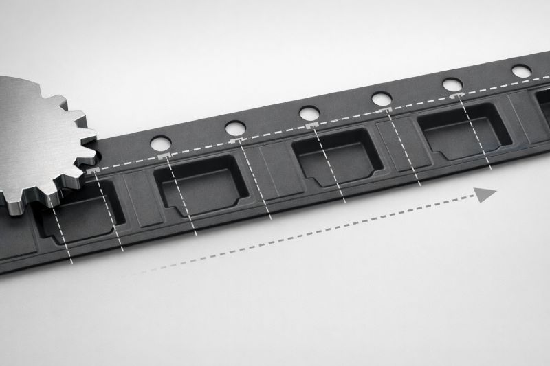
When the D1 hole position deviates, even slightly, the feeder no longer advances the tape by a true, repeatable distance. The result is feeding instability, pocket-to-nozzle misalignment, and cumulative positioning error over long runs. At low speeds, these issues may appear tolerable. In high-speed SMT production, they are not.
This is why the D1 hole should be understood as a positional datum, not a secondary detail. It defines how accurately the tape moves, how consistently pockets arrive under the pick-up point, and how reliable the entire feeding process is—especially when pitch accuracy becomes critical.
What Is the D1 Hole in Carrier Tape?
The D1 hole in carrier tape is the sprocket hole used for tape indexing in SMT feeder systems. It is located along the edge of the tape and is manufactured at a fixed interval that corresponds directly to the tape pitch. During operation, the feeder’s sprocket engages these holes to pull the tape forward in precise, repeatable steps.
From an engineering standpoint, the D1 hole is not a component-retention feature and has no role in holding or protecting the device. It is also not interchangeable with pocket geometry or other hole types sometimes found in tape designs. Its sole function is mechanical indexing.
Because the feeder references the D1 hole—not the pocket—the positional accuracy of every pocket ultimately traces back to the accuracy of the D1 hole pattern. This is why it is treated as a system-level reference rather than a simple punched opening.
Function of the D1 Hole in SMT Feeding
In an SMT feeder, the D1 hole is the mechanical interface between the tape and the drive system. The feeder sprocket engages each D1 hole to advance the tape by one pitch increment. This means the feeder does not “see” pockets directly—it trusts the D1 hole pattern to define where every pocket should be.
Because of this, the relative position between the D1 hole and the pocket center is critical. If that relationship is off, the feeder may advance the tape correctly according to the holes, yet the pocket will arrive slightly early or late at the pick-up position. Over multiple advances, small deviations can accumulate into noticeable misalignment.
In practical terms, feeding accuracy is determined less by how well pockets are formed, and more by how consistently the D1 holes control tape movement. This is why, in engineering-driven tape design, the D1 hole is treated as the indexing master, while pockets are designed relative to it—not the other way around.
Standard D1 Hole Size According to EIA-481
The D1 hole size used in carrier tape systems is defined within the EIA-481 standard to ensure basic compatibility between tape and feeder mechanisms. From an engineering perspective, this standard does not exist to optimize performance in every scenario—it exists to establish a common mechanical language between tape manufacturers and SMT equipment.
By specifying a nominal D1 hole size and tolerance range, EIA-481 ensures that feeder sprockets can reliably engage the tape without slipping, skipping, or excessive wear. This baseline consistency is what allows carrier tapes from different sources to function on mainstream feeders without custom adjustment.
However, it is important to understand the limitation of standards. Compliance does not automatically equal optimal performance. Material behavior, forming processes, tape thickness, and operating speed all influence how a “standard” hole performs in real production. In high-speed or high-precision applications, a D1 hole that is technically within spec may still introduce feeding variability.
This is why experienced engineers treat EIA-481 as a starting framework, not a final design decision—especially when system tolerances are tight or production speeds are aggressive.
Relationship Between D1 Hole, Pitch and Pocket
To understand carrier tape behavior as a system, the D1 hole, pitch, and pocket must be viewed as interdependent elements, not isolated features. Each serves a distinct role, but their alignment determines whether the tape feeds accurately or merely “moves.”
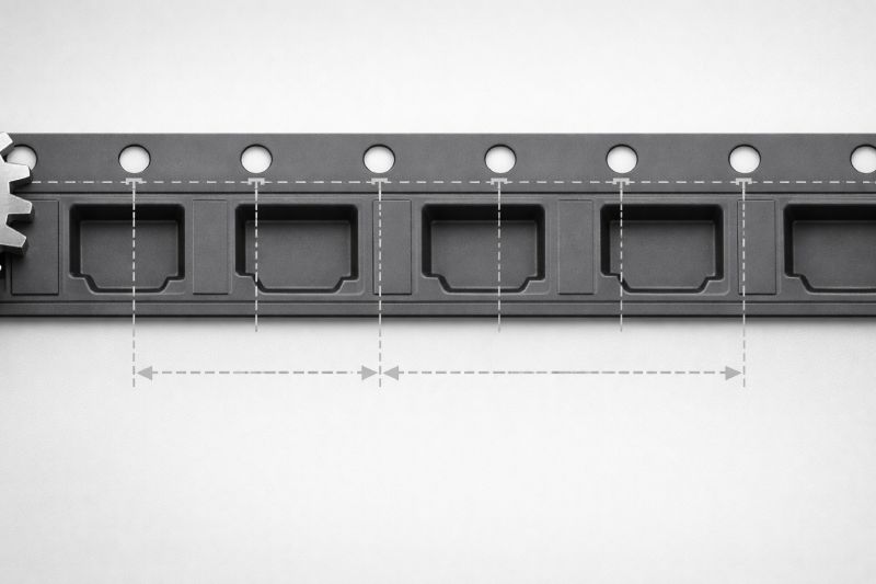
The D1 hole is the indexing reference. It defines where the feeder applies force and how far the tape advances each cycle. Pitch is the rhythmic unit of that movement—the fixed distance between successive indexing points. Pockets, in contrast, are passive structures: they only arrive at the correct position if the indexing system is correct.
This means pockets are not the true reference; they are positioned relative to the D1 hole pattern. When pitch is consistent but the hole-to-pocket relationship is misaligned, the feeder still advances smoothly, yet pick accuracy suffers. When hole spacing varies, the issue becomes more severe, leading to cumulative error across the reel.
From an engineering standpoint, reliable feeding comes from treating these three features as a single coordinated geometry, not three separate dimensions.
Does Every Carrier Tape Need a D1 Hole?
Not every carrier tape application requires a D1 hole, but most automated SMT environments depend on it. The necessity of a D1 hole is determined by how the tape is driven, indexed, and synchronized with the pick-and-place process.
In low-speed or semi-manual setups, tape advancement may rely on friction drive, manual indexing, or simplified feeders that do not reference sprocket holes. In these cases, the absence of a D1 hole may not immediately impact usability or yield. Similarly, certain non-traditional tape formats or specialty packaging solutions are designed around alternative drive mechanisms.
However, once production shifts toward continuous, high-speed, or high-volume SMT, the D1 hole becomes functionally indispensable. Automated feeders require a repeatable mechanical reference to maintain alignment over thousands of index cycles. Without a sprocket hole, positional accuracy becomes difficult to control and even harder to maintain consistently.
In practice, the question is less about whether a D1 hole is mandatory, and more about how much feeding precision the application demands. As precision requirements rise, reliance on the D1 hole rises with them.
Common D1 Hole Design Issues
Many carrier tape feeding problems trace back to the D1 hole—not because it is missing, but because it is treated as a secondary feature during design or forming. One common issue is hole-to-pocket misalignment, where the D1 hole pattern is technically consistent, but its positional relationship to the pocket center drifts. The feeder advances correctly, yet the pick position slowly walks off target.
Another frequent problem is inconsistent hole spacing. Even small variations between successive D1 holes can introduce micro-errors that accumulate over long runs, especially at high indexing speeds. These errors are often invisible in short tests but appear during full-reel production.
Material deformation during forming is also a factor. Thin or flexible materials may stretch, shrink, or rebound after punching, subtly altering hole geometry and position. When these effects are not accounted for, the final tape may meet visual expectations while failing mechanically.
The most overlooked issue is cumulative error—the assumption that minor deviations cancel out. In reality, indexing errors tend to add up, not disappear, making D1 hole consistency a system-level concern rather than a cosmetic one.
D1 Hole Considerations in Custom Carrier Tape Design
In custom carrier tape projects, the D1 hole often becomes a design variable, not a fixed assumption. This typically happens when standard pitch no longer applies, component geometry forces non-standard pocket placement, or the tape must perform reliably under higher-than-normal SMT speeds.
When pitch is customized, the D1 hole spacing must be re-evaluated as part of the indexing system—not simply scaled from a standard layout. Any change to pocket orientation or component center of gravity also alters the hole-to-pocket reference relationship, which directly affects pick accuracy. In these cases, copying a standard D1 hole pattern without system-level adjustment is a common source of feeding instability.
High-yield production adds another layer of sensitivity. As placement speed increases, tolerance for indexing error shrinks. A D1 hole design that works in trial runs may become a bottleneck in mass production if deformation, material recovery, or long-run consistency are not considered.
This is why custom carrier tape design treats the D1 hole as an engineering decision, not a default feature—often requiring coordinated review through detailed drawings and feeder assumptions.
Summary
At its core, the D1 hole is the indexing reference that governs how a carrier tape moves. It does not hold components, and it does not define pocket shape—but it determines whether every pocket arrives at the correct position, cycle after cycle. This is why D1 hole accuracy has a direct impact on feeder stability, placement consistency, and long-run reliability.
The D1 hole is often overlooked because it appears simple. In reality, it is one of the most system-critical features in carrier tape design, especially as SMT speeds increase and tolerances tighten. Small deviations that seem harmless in isolation can accumulate into real production losses.
If your goal is better feeding stability or higher placement yield, the next step is to understand how indexing interacts with pitch—and when standard assumptions no longer apply.



 Emial
Emial John Mr


