








Carrier Tape Feeding Issues Explained: Causes, Symptoms & Engineering Insights
What Are Carrier Tape Feeding Issues?
Carrier tape feeding issues refer to a range of instabilities that occur during the component feeding process in SMT assembly, rather than a single, isolated failure. In practice, “feeding issues” describe situations where components are no longer delivered to the pick-up position with consistent timing, position, or orientation.
These issues are system-level behaviors involving the interaction between the carrier tape, the feeder mechanism, the packaged component, and the operating speed of the SMT line. Importantly, feeding issues do not always cause an immediate line stop. More often, they appear as a gradual loss of stability—such as occasional mis-picks, slight component shifts, or increasing feeder interventions over time.
Because of this, feeding issues are frequently misunderstood or misattributed to one part of the system. A proper understanding requires viewing tape and reel packaging as a dynamic process, as explained in Carrier Tape and Reel Packaging Explained and Tape and Reel Packaging for SMT Components.
Why Feeding Issues Occur in SMT Assembly
Feeding issues occur in SMT assembly because component feeding is a dynamic, high-speed mechanical process, not a static positioning task. During operation, the carrier tape is continuously indexed, tensioned, peeled, and released while the feeder repeats the same motion thousands of times per hour. Under these conditions, even minor deviations can be amplified.
At higher placement speeds, small inconsistencies accumulate—slight pitch variation, marginal sprocket hole alignment, subtle pocket deformation, or timing differences in cover tape release. Individually, these factors may remain within tolerance. Together, they reduce the system’s ability to maintain consistent pick-up conditions.
Most feeding issues are therefore not caused by a single defect, but by stacked tolerances and repeated motion. This explains why a tape may appear acceptable during inspection or short test runs, yet show instability in continuous production. Understanding this cumulative behavior is critical when evaluating dimensions such as pitch consistency and indexing accuracy, as discussed in Carrier Tape Pitch Explained and Carrier Tape D1 Hole Explained.
Common Symptoms of Carrier Tape Feeding Issues
Carrier tape feeding issues are most easily identified through observable symptoms on the SMT line, rather than through dimensional checks or material specifications. These symptoms often appear intermittently at first, making them difficult to trace to a single cause.
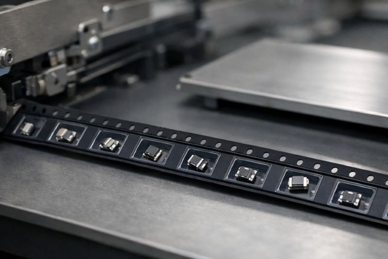
One of the most common signs is mis-pick or missed pick, where the nozzle fails to pick up the component even though it appears correctly positioned. This is frequently followed by component rotation or slight shifting within the pocket, causing orientation errors at the pick-up point. In many cases, the component is still present, but no longer centered or stable.
Another typical symptom is jamming or intermittent stopping of the feeder. Unlike hard mechanical failures, this may occur only after several cycles, then disappear temporarily after manual intervention. Similarly, operators may observe inconsistent pick positions, where the nominal pick location drifts slightly over time, leading to placement accuracy issues downstream.
What makes these symptoms especially challenging is that they rarely occur consistently from the start of production. Instead, they tend to worsen as speed increases, runtime extends, or feeder adjustments accumulate. For engineers, recognizing these early signals is critical—they often indicate a system approaching its tolerance limit, rather than an isolated defect that can be corrected with a simple adjustment.
Root Causes of Carrier Tape Feeding Issues
At the engineering level, carrier tape feeding issues rarely stem from a single fault. Instead, they emerge from cause-and-effect chains within the feeding system, where small deviations interact and compound over time. Understanding these root causes requires breaking the problem down into key structural and dimensional factors rather than treating symptoms in isolation.
Pitch-Related Issues
Pitch inconsistency is one of the most common underlying contributors to feeding instability. Even when individual pitch measurements appear within tolerance, small variations can accumulate across multiple indexes. As the feeder advances the tape repeatedly, these cumulative errors shift the effective pick position, increasing the likelihood of mis-picks or component offset. This is especially critical in high-speed SMT lines, where there is little tolerance for positional drift.
Sprocket Hole & Indexing Issues
Sprocket hole accuracy—particularly D1 hole positioning—directly affects how precisely the feeder indexes the tape. Minor misalignment between the sprocket hole and pocket center can cause uneven advancement, timing mismatch, or micro-slippage during indexing. Over time, this leads to inconsistent pocket presentation at the pick-up location, even if the tape appears visually acceptable.
Pocket Design & Retention Problems
Pocket geometry plays a critical role in component stability during feeding. Inadequate retention, excessive clearance, or inconsistent pocket depth can allow components to shift under vibration or during cover tape peeling. Conversely, overly tight or complex pockets may resist smooth release, disturbing component position at the moment of pick. These issues are design-related and cannot be corrected through feeder adjustment alone.
Related: Carrier Tape Design
Taken together, these factors explain why feeding issues persist despite repeated line tuning. Without addressing the structural root causes, the system remains vulnerable to instability as speed, runtime, or production volume increases.
Material-Related Feeding Problems
Material selection is rarely the primary cause of carrier tape feeding issues, but it often amplifies existing weaknesses in the feeding system. Different carrier tape materials respond differently to mechanical stress, temperature, and repeated motion, which directly affects feeding stability over time.
PS carrier tape, for example, offers good formability but relatively low rigidity. Under continuous indexing and peel force, pocket walls may flex slightly, reducing their ability to maintain consistent component position. This makes PS more sensitive to pocket geometry and retention design, particularly in deeper or more complex pockets.
PET carrier tape provides improved dimensional stability and better resistance to deformation, which helps maintain pocket shape during feeding. However, PET’s higher stiffness can also transfer vibration more directly to the component if retention is insufficient. In high-speed lines, this may lead to subtle component shifting rather than visible deformation.
PC carrier tape offers the highest rigidity and shape retention among common materials, making it more tolerant of demanding feeding conditions. In many cases, projects that experience persistent feeding instability see immediate improvement after switching to PC—not because the material “fixes” the system, but because it reduces deformation and variability under dynamic loading.
This is why material changes sometimes appear to “solve” feeding issues. In reality, the underlying design remains unchanged; the material simply narrows the system’s tolerance window and restores stability.
Cover Tape & Peel Force Impact on Feeding
Cover tape behavior plays a critical but often underestimated role in carrier tape feeding stability. While peel force is commonly specified and measured, lower peel force does not automatically result in better feeding performance. In dynamic SMT operation, the timing and consistency of cover tape release are just as important as the absolute force value.
If peel force is too low, the cover tape may release unpredictably, allowing components to lift, tilt, or shift before the pick-up nozzle engages. Conversely, excessive peel force can introduce sudden release events, momentarily disturbing the pocket or component position at the point of exposure. In both cases, the issue is not the force itself, but how and when the component is released during feeder indexing.
Another frequent cause of feeding instability is cover tape incompatibility. Mismatched adhesive systems, improper sealing conditions, or unsuitable carrier tape surfaces can lead to uneven peel behavior across the reel. This results in inconsistent exposure timing from pocket to pocket, even when the carrier tape dimensions are within tolerance.
Because peel behavior is directly tied to feeder motion, these effects become more pronounced at higher speeds. What appears stable during low-speed trials may degrade rapidly in production. For this reason, cover tape selection and peel behavior should always be evaluated as part of the feeding system—not as an isolated packaging parameter.
Feeder, Speed & System Interaction
Carrier tape feeding issues are often mistakenly attributed solely to the tape itself, when in reality they arise from interactions across the entire feeding system. The feeder, operating speed, and machine dynamics all play decisive roles in how consistently a tape performs on the SMT line.
Feeder mechanisms differ in how they index tape, control tension, and manage cover tape peeling. As a result, the same carrier tape can behave very differently on different feeders or production lines. Variations in indexing accuracy, clamp timing, or peel angle may push an otherwise acceptable tape beyond its stable operating window.
Speed further reduces system tolerance. As placement rates increase, the time available for the tape, pocket, and component to settle into a stable state decreases. Vibration, inertia, and transient forces become more influential, turning minor dimensional or material variations into visible feeding problems. This is why feeding issues often appear only after line speed is increased, even though nothing else has changed.
From an engineering perspective, feeding stability should never be evaluated in isolation. A carrier tape that performs well at moderate speed on one line may require tighter tolerances, different materials, or design adjustments to remain stable in a higher-speed or less forgiving system. Understanding this interaction is key to realistic validation and reliable scale-up.
Why Feeding Issues Often Appear After Scale-Up
One of the most common and frustrating observations in SMT production is that feeding performs well during sampling but degrades after scale-up. This does not indicate a sudden quality drop; rather, it reflects how dynamic errors accumulate under real production conditions.
During pilot runs or small batches, the system operates for limited time at controlled speeds, often with heightened attention from operators. Under these conditions, marginal inconsistencies in pitch, pocket retention, or peel behavior may not reach a visible threshold. Once production scales up, however, runtime increases, speed is optimized, and vibration and tension become more consistent and repetitive.
As volume grows, cumulative indexing error, gradual component shifting, and subtle material deformation are amplified across thousands of cycles. Small deviations that were statistically insignificant in short runs become systematic in mass production. This is why issues such as intermittent mis-picks or feeder intervention often emerge only after hours—or days—of continuous operation.
Scale-up also introduces variability across reels, lots, and feeders. A system that tolerates small differences at low volume may no longer have sufficient margin once throughput increases. Recognizing feeding issues as a scale-dependent phenomenon is essential for realistic validation and long-term process stability.
Engineering Considerations to Reduce Feeding Issues
Reducing carrier tape feeding issues is less about applying quick fixes and more about adopting the right engineering mindset throughout the project lifecycle. Stable feeding is typically the result of decisions made early—in design, material selection, and validation—rather than adjustments made on the production floor.
During the design stage, engineers should consider how pocket geometry, pitch accuracy, and sprocket hole alignment will behave under dynamic conditions, not just static measurement. Designs that appear acceptable on drawings may leave too little margin once vibration, peel timing, and high-speed indexing are introduced.
Material selection should be approached as a stability factor, not a cost-only decision. Different materials influence how well pocket shape and positional accuracy are maintained over time. Choosing a material that supports the intended speed and component sensitivity can significantly reduce the risk of marginal feeding behavior.
In the validation phase, testing should reflect real production conditions. This includes running at target speeds, evaluating peel behavior continuously, and observing performance across extended cycles rather than short trials. The goal is not to prove that feeding works once, but to confirm that the system remains stable as tolerances stack and time progresses. This engineering-focused approach is the most reliable way to prevent recurring feeding issues.
When Feeding Issues Indicate the Need for Custom Carrier Tape
Not all feeding issues can—or should—be resolved through line adjustment or parameter tuning. In many cases, recurring instability is a signal that the standard carrier tape configuration no longer provides sufficient margin for the application.
One clear indicator is when a standard tape passes initial validation but continues to show inconsistent feeding after multiple rounds of optimization. If feeder settings, speed reduction, and cover tape changes fail to produce stable results, the issue is likely structural rather than operational. Another strong signal is when feeding problems scale disproportionately with speed—minor issues at moderate speed becoming severe at higher throughput.
Projects that are highly sensitive to yield loss or placement accuracy are especially vulnerable. Even small, intermittent mis-picks can translate into unacceptable scrap rates or rework costs. In these cases, relying on a generic tape design often shifts risk downstream rather than eliminating it.
Custom carrier tape becomes relevant when stability must be engineered into the packaging itself—through optimized pocket geometry, tighter pitch control, or material selection matched to the feeder and component behavior. The goal is not customization for its own sake, but restoring system balance where standard solutions no longer suffice.
Summary: Understanding Feeding Issues as a System Problem
Carrier tape feeding issues are best understood as system-level problems, not isolated defects in a single component or parameter. Tape design, material behavior, cover tape interaction, feeder mechanics, and operating speed all contribute to overall stability, especially under high-speed, high-volume conditions.
When feeding issues are approached only as local failures, they tend to reappear in different forms as production scales or conditions change. By focusing on underlying causes and cumulative effects, engineers can identify where system margins are insufficient and address them proactively.
A well-matched carrier tape—designed, specified, and validated with the full feeding system in mind—forms the foundation of reliable SMT operation. Understanding why feeding issues occur is the first step toward preventing them from becoming recurring production risks.



 Emial
Emial John Mr


