








How to Choose the Right Carrier Tape for SMT Components
Why Choosing the Right Carrier Tape Matters in SMT Packaging
In SMT packaging, carrier tape is often mistaken for a passive packaging material. In reality, it is an active part of the assembly process. The way a component is held, presented, and released by the carrier tape directly affects how smoothly it moves through feeding, pick-and-place, and reflow. When the carrier tape is poorly selected, problems rarely stay isolated at the packaging stage—they surface on the production line.
An incorrect carrier tape choice can lead to unstable feeding, mis-picks, component rotation, or placement errors, all of which reduce yield and slow down throughput. These issues are not minor inconveniences; they translate into machine downtime, rework, and higher production costs. From an engineering perspective, carrier tape should be treated as part of the process design, not as an afterthought.
Understanding this mindset is essential before making any selection decisions. If you need foundational context, the Carrier Tape Guide and Carrier Tape and Reel Packaging Explained provide a helpful starting point for how carrier tape integrates into the SMT ecosystem.
Start with the Component: What Really Determines Carrier Tape Selection
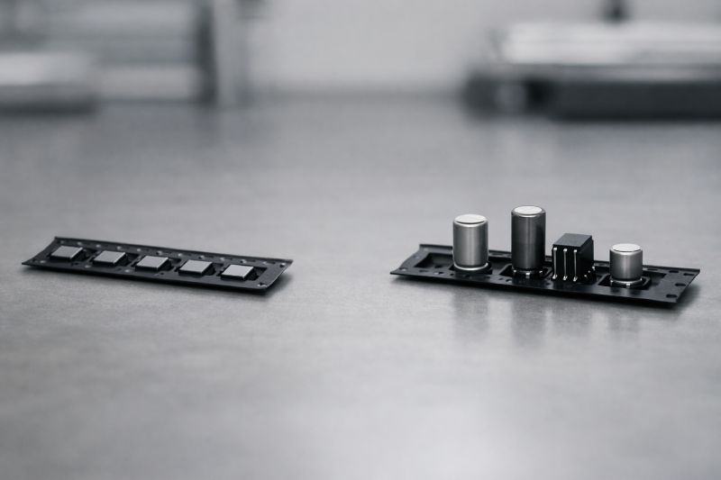
Every carrier tape decision should begin with the component itself. Not with tape type, not with material, and not with what was used last time—but with how the component behaves physically and functionally throughout the SMT process. Carrier tape exists to serve the component, not the other way around.
Component size and geometry define the basic pocket envelope, but they are only the starting point. Weight and center of gravity influence how securely the component sits during indexing and acceleration inside the feeder. A part that appears dimensionally stable on paper may still tilt, rotate, or shift if its mass distribution is uneven. Fragility and surface sensitivity add another layer of constraint: sharp edges, exposed leads, lenses, or coated surfaces often require controlled clearance and gentler retention to avoid damage or cosmetic defects.
Orientation requirements are equally critical. Many components must be presented in a fixed, repeatable orientation for reliable pick-up and placement. If the pocket geometry does not actively control orientation, the feeder and pick-and-place system are forced to compensate—often unsuccessfully.
The key principle is simple but frequently overlooked: carrier tape is a structural interface designed around the component’s physical behavior. When selection decisions are driven primarily by the component’s real-world characteristics, downstream choices about tape type, material, and dimensions become far more logical—and far less risky.
Carrier Tape Types: Embossed vs Punched — Which Should You Choose?
Choosing between embossed and punched carrier tape is not a question of which type is “better,” but which one aligns with your component’s requirements and your production realities. The decision should be driven by function first, and cost second.
Embossed carrier tape is typically preferred when components require precise pocket geometry, consistent orientation, or higher retention stability. Because the pockets are thermoformed, embossed tape can be engineered to match complex shapes, control depth accurately, and support components with uneven geometry or sensitive features. This makes it well suited for high-speed SMT lines, fine-pitch components, and applications where feeding consistency and placement accuracy are critical.
Punched carrier tape, on the other hand, can make sense when component geometry is simple and flat, and when production volumes or cost constraints dominate the decision. Since pockets are mechanically punched through the base material, design flexibility is more limited, but tooling costs and lead times may be lower for certain standardized parts. For components that do not demand tight orientation control, punched tape can be a practical choice.
From an engineering standpoint, the real trade-off is between structural control and economic efficiency. When process stability, yield, and automation performance matter most, embossed carrier tape is often the safer path. When tolerances are forgiving and volumes justify it, punched tape may be sufficient. Understanding where your application sits on that spectrum is what leads to the right choice.
Material Selection: PS vs PET vs PC — How to Decide
Material choice is one of the most critical—and most misunderstood—parts of carrier tape selection. Rather than comparing materials side by side, it is more effective to follow a decision path based on what your process actually demands.
If cost efficiency and high-volume production dominate your priorities, PS (polystyrene) carrier tape is often the starting point. PS is economical and widely used for standard components where pocket geometry is simple and mechanical stress during feeding is limited. In stable, lower-speed SMT environments, PS can perform reliably when its structural limits are respected.
When balance between cost and performance matters, PET becomes a strong candidate. PET offers improved dimensional stability, better resistance to deformation, and more consistent feeding behavior compared to PS. This makes it suitable for components with moderate weight, tighter pocket tolerances, or lines where feeding stability cannot be compromised but PC-level precision is not strictly required.
PC carrier tape is chosen when precision, speed, and process reliability are critical. PC provides superior stiffness, thermal stability, and forming accuracy, which directly supports high-speed feeders, fine-pitch components, and demanding pick-and-place accuracy. In advanced SMT lines, PC is often selected not for cost reasons, but because it reduces risk, variability, and long-term process drift.
The key insight is that material selection is not about preference—it is about matching material behavior to process expectations. Resources such as PS Carrier Tape, PET Carrier Tape, PC Carrier Tape, and the Carrier Tape Materials Guide can help validate these decisions within a broader engineering context.
Pocket Design Considerations That Impact Carrier Tape Choice
Pocket design is where carrier tape selection and mechanical reality meet. Even with the right tape type and material, an improperly designed pocket can undermine the entire SMT process. The goal of pocket design is not simply to “fit” the component, but to control how it behaves under motion.
Pocket depth must be evaluated relative to component height, but deeper is not automatically better. Excessive depth can make pick-up inconsistent, while insufficient depth increases the risk of components lifting, rotating, or escaping during feeding. The correct depth creates a stable center of gravity while still allowing reliable vacuum access during pick-and-place.
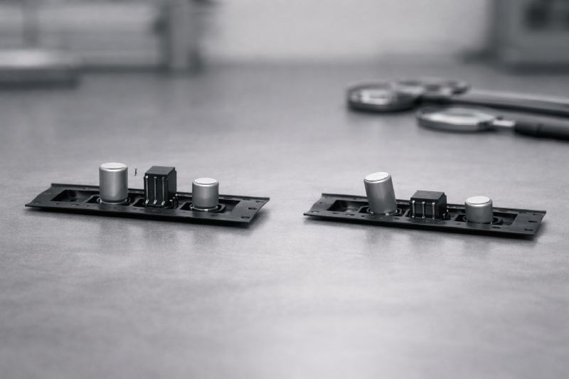
Clearance and retention logic are equally important. A common mistake is designing pockets that are just large enough to accept the component dimensions. This “just fits” approach ignores dynamic forces such as vibration, acceleration, and deceleration inside the feeder. Proper pocket clearance must account for these forces while using pocket walls, corner geometry, or contact points to gently restrain movement without stressing the component.
In practice, pocket design should be viewed as an active control mechanism, not a passive container. Decisions made at this stage directly influence feeding stability, placement accuracy, and yield. For deeper insight into how pocket geometry ties into overall selection, the Carrier Tape Design Guide and Embossed Carrier Tape Explained provide valuable engineering context.
Pitch, D1 Hole & Dimensions: How Specifications Influence Selection
Dimensional specifications are often treated as fixed parameters, but in reality, they play a decisive role in carrier tape selection and SMT line stability. Pitch, D1 hole configuration, and overall tape dimensions together determine how well the carrier tape interfaces with feeders and pick-and-place equipment.
Pitch directly affects feeder compatibility and indexing accuracy. A pitch that is theoretically acceptable but poorly matched to the feeder’s mechanical rhythm can introduce cumulative positioning errors over long runs. For high-speed or high-precision lines, even small pitch inconsistencies can lead to mis-picks or placement drift.
The D1 sprocket hole is critical for feeding stability. Its size, position, and consistency govern how smoothly the tape advances under tension. Poorly aligned or inaccurately formed D1 holes can cause uneven advancement, sudden stops, or micro-slippage, all of which disrupt component presentation at the pick-up point. From an engineering standpoint, D1 hole quality is as important as pocket design.
Tape width, pocket-to-edge distance, and spacing constraints further define whether a carrier tape will run reliably on a given SMT line. These dimensions must align with feeder specifications, reel systems, and line layouts.
Cover Tape Compatibility: A Critical Part of Carrier Tape Selection
Carrier tape cannot be selected in isolation. Its performance on the SMT line is inseparable from the cover tape used to seal and protect the components. Ignoring this relationship is one of the most common causes of feeding and placement problems.
Cover tape compatibility affects how consistently components are retained during transport and how cleanly they are released at pick-up. Peel force must be carefully balanced: too low, and components may shift or escape during feeding; too high, and peeling becomes unstable, leading to component lift, rotation, or feeder interruptions. This balance depends on both the carrier tape material and the cover tape’s adhesive and sealing characteristics.
Sealing temperature, pressure, and dwell time also interact with carrier tape material behavior. A carrier tape that performs well mechanically can still fail if the cover tape does not bond or release in a controlled way. For this reason, carrier tape and cover tape should always be evaluated as a system rather than as independent items.
SMT Process Factors That Affect Carrier Tape Choice
Even with the same component, carrier tape selection can change dramatically depending on the SMT process it runs through. Process conditions define how much mechanical and positional stress the carrier tape must withstand, and overlooking these factors often leads to unstable production.
SMT speed is one of the most influential variables. Higher line speeds increase acceleration forces during indexing and peeling, which places greater demands on pocket stability, material stiffness, and D1 hole accuracy. A carrier tape that performs acceptably on a low-speed line may fail once speeds increase.
Feeder type also matters. Different feeder designs apply different tension, peel angles, and indexing mechanics to the tape. What feeds smoothly in one feeder system may behave unpredictably in another. Pick-and-place accuracy further tightens the requirements, especially for small, lightweight, or asymmetrical components that rely heavily on precise presentation.
Production volume completes the picture. Short runs may tolerate minor inefficiencies, but high-volume or continuous production amplifies even small selection mistakes into significant yield loss or downtime. The key takeaway is simple: carrier tape selection is process-dependent. The same component may require different carrier tape solutions on different SMT lines, and recognizing this early is essential for stable, scalable manufacturing.
When Standard Carrier Tape Is Not Enough
Standard carrier tape solutions are designed to cover a wide range of common components and applications. However, there are clear engineering boundaries where standard options begin to fail. Recognizing these limits is essential before problems appear on the SMT line.
One signal is inconsistent feeding that cannot be resolved through feeder adjustment or process tuning. If components shift, rotate, or lift despite meeting nominal size requirements, the issue often lies in pocket geometry that does not properly control the component’s center of gravity or orientation. Another indicator is damage or cosmetic defects caused by contact points that are acceptable in standard designs but unsuitable for fragile or surface-sensitive components.
High-speed lines and tight placement tolerances also push standard carrier tape beyond its comfort zone. As speeds increase, small variations in pocket depth, material stiffness, or dimensional consistency become amplified. In these cases, a custom solution is not about optimization—it is about maintaining process stability.
Common Mistakes When Choosing Carrier Tape
Most carrier tape problems do not come from lack of options, but from flawed selection logic. These mistakes often seem reasonable at the decision stage, yet they surface later as feeding instability, yield loss, or recurring line adjustments.
One common error is focusing only on component dimensions. While size matters, it tells only part of the story. Ignoring weight distribution, surface sensitivity, or orientation requirements often leads to pockets that technically fit but fail under real SMT conditions. Another frequent mistake is selecting carrier tape without considering the actual SMT process. Line speed, feeder type, and placement accuracy requirements can radically change what “works,” even for the same component.
Cost-driven decisions are another risk area. Choosing the lowest-cost material or standard design may appear efficient upfront, but repeated stoppages, rework, or damaged components quickly erase those savings. Equally problematic is overlooking cover tape compatibility. Treating cover tape as an afterthought can introduce peel and release issues that undermine an otherwise well-chosen carrier tape.
Avoiding these mistakes requires shifting perspective: carrier tape selection is an engineering decision, not a packaging purchase. When choices are made with process reality in mind, long-term stability becomes achievable rather than accidental.
A Practical Step-by-Step Carrier Tape Selection Process
A reliable carrier tape decision is best made through a structured process rather than intuition or past habits. Breaking the selection into clear steps helps reduce risk and makes validation more predictable.
Step 1: Analyze component characteristics
Start by understanding the component’s size, geometry, weight distribution, fragility, and orientation requirements. This establishes what the pocket must physically control and protect.
Step 2: Define SMT process constraints
Evaluate line speed, feeder type, pick-and-place accuracy, and production volume. These factors determine how much mechanical stress and precision the carrier tape must support.
Step 3: Choose the appropriate tape type
Based on the component and process, decide whether embossed or punched carrier tape provides the required level of control and stability.
Step 4: Select the material
Match material behavior—PS, PET, or PC—to the performance expectations of the SMT line rather than defaulting to cost or familiarity.
Step 5: Validate through trials
Before full-scale production, confirm performance with feeding and placement tests. Real-world validation is the final safeguard against hidden issues.
This step-by-step approach turns carrier tape selection into a repeatable engineering workflow instead of a trial-and-error exercise.
Summary: Choosing Carrier Tape as an Engineering Decision
Carrier tape selection should never be reduced to a packaging preference or a cost comparison. It is a structural engineering decision that directly shapes feeding stability, placement accuracy, and overall SMT yield. Every variable—component geometry, pocket design, material behavior, pitch accuracy, cover tape interaction, and line speed—forms part of a connected system.
When carrier tape is chosen without considering this system, problems surface downstream in the form of mis-picks, rotation, downtime, and rework. When it is selected through a structured, component-first and process-aware approach, it becomes a stabilizing interface between design and manufacturing.
In practical terms, the right carrier tape is the one that supports consistent production under real operating conditions—not just one that meets dimensional specifications. Treating carrier tape as part of the SMT engineering architecture is what ultimately enables predictable, scalable, and high-yield manufacturing.



 Emial
Emial John Mr


