








When to Use Custom Carrier Tape Instead of Standard
What Is Considered a Standard Carrier Tape
In the electronics packaging industry, a standard carrier tape refers to pre-defined tape formats designed around widely used component categories and feeder systems. These tapes follow established conventions for pocket shape families, pitch patterns, and sprocket alignment that are broadly compatible with mainstream SMT equipment. While there are variations across materials and suppliers, the underlying geometries are not engineered for a specific component—they are designed to cover a wide range of “typical” parts.
Standard carrier tapes work because they sit within proven manufacturing windows. The pocket structures, tape stiffness, and feeding behavior have been validated over years of use across high-volume programs. For components with common outlines, predictable tolerances, and mature assembly processes, these off-the-shelf formats usually provide sufficient retention and stable feeding performance without additional design effort.
For foundational concepts and terminology, see Carrier Tape Guide and Embossed Carrier Tape Explained.
Why Standard Carrier Tape Works in Most SMT Applications
Standard carrier tape remains the default choice in SMT packaging because it aligns well with how most assembly lines are designed to operate. The formats are mature, widely supported by feeder manufacturers, and predictable in behavior across different machines and production environments. This maturity reduces uncertainty during setup and scale-up, which is critical for stable mass production.
For components with simple, well-understood geometries, standard pockets usually provide adequate positional control without over-constraining the part. Combined with established cover tape options, they offer acceptable retention force and reliable peel behavior at common line speeds. From a manufacturing perspective, this balance of performance and consistency is hard to beat.
Cost and availability also play a major role. Standard tapes eliminate tooling lead time, simplify sourcing, and reduce upfront engineering effort. When component dimensions fall comfortably within known tolerance ranges and the SMT process itself is already optimized, a standard carrier tape is often the most rational engineering decision—not a compromise, but a proven solution that fits the application as intended.
The Hidden Limitations of Standard Carrier Tape
The limitations of standard carrier tape rarely appear at the specification stage—they surface at the failure boundary, when a project is pushed beyond what those formats were originally designed to handle. Standard pockets are built around averaged component profiles, which means they struggle to properly constrain parts with asymmetrical shapes, unusual thickness distribution, or delicate features that require controlled support rather than generic containment.
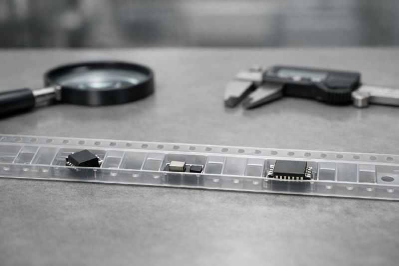
Pitch and sprocket hole alignment are another invisible constraint. Because these parameters are fixed, they cannot be tuned to compensate for component center-of-gravity shifts or feeder dynamics at higher speeds. As SMT line speed increases, small inconsistencies in pocket fit or tape guidance become amplified, showing up as vibration, component rotation, or intermittent misfeeds.
Perhaps the most underestimated issue is tolerance accumulation. In low-volume or prototype runs, standard tape may appear acceptable. In mass production, however, minor dimensional mismatches stack up across thousands of cycles. What initially looks like a manageable variation can turn into unstable feeding behavior, reduced placement accuracy, or unexplained yield loss—issues that are difficult to trace back to the carrier tape once the line is running.
Clear Engineering Signs You Need Custom Carrier Tape
The need for custom carrier tape is rarely driven by preference—it is usually triggered by repeatable engineering signals that standard formats can no longer absorb. One of the earliest signs is inconsistent component seating. When parts do not sit securely or return to a stable orientation within standard pockets, operators may compensate with process tweaks, but the root cause is often geometric mismatch rather than setup error.
Another indicator is persistent feeding instability despite adjustments to cover tape type, peel angle, or tension. If misfeeds, rotations, or component shifts continue after reasonable process optimization, the limitation is likely in the pocket and pitch design itself. High-speed SMT lines make this especially visible, as increased acceleration magnifies even small retention or guidance issues.
Component geometry is the final, and often decisive, signal. Parts with irregular outlines, sensitive surfaces, or tight positional requirements can exceed the effective tolerance range of standard carrier tape. When maintaining placement accuracy depends on “getting lucky” with pocket fit, custom carrier tape becomes an engineering control measure—designed to stabilize the system rather than react to its failures.
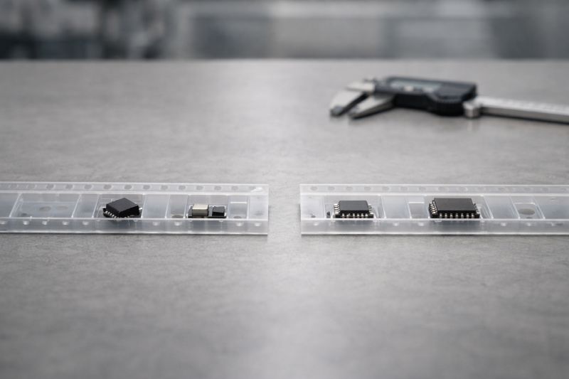
Custom Carrier Tape Solves Problems Standard Tape Cannot
Custom carrier tape addresses limitations at the system level, where stability is designed rather than assumed. Instead of forcing a component to adapt to a generic pocket, pocket geometry is engineered around the actual shape, mass distribution, and contact points of the part. This ensures consistent seating and controlled movement throughout feeding, peeling, and placement.
Pitch and D1 hole positioning can also be optimized to match feeder behavior, reducing micro-shifts that occur when standard spacing interacts poorly with high-speed motion. Rather than relying on compensations elsewhere in the process, alignment and guidance are built into the tape itself. This becomes increasingly important as line speeds rise and placement tolerances tighten.
Most critically, retention force is no longer a guess based on trial-and-error cover tape selection. In custom designs, retention is a defined parameter—balanced to hold the component securely while allowing predictable release at the pick point. The result is a more stable feeding system where repeatability is engineered upfront, not recovered through downstream adjustments.
Engineering Trade-Offs of Custom Carrier Tape
Custom carrier tape is an engineering decision, not a default upgrade, and it comes with clear trade-offs that must be weighed early. The most immediate factor is lead time. Designing and validating a new pocket and pitch configuration requires upfront coordination, sampling, and iteration before production can begin. This is time that standard tape simply does not require.
Tooling cost is another reality. Custom embossing tools introduce non-recurring expense, which must be justified by volume, yield improvement, or process stability gains. For low-run programs, this investment may outweigh the operational benefits, even if the technical solution is superior.
Finally, custom tape demands deeper engineering involvement. Component data must be reviewed, tolerances understood, and feeding behavior validated through testing. This effort is intentional: custom solutions reduce uncertainty in production, but only when the design assumptions are verified. In this sense, customization represents a shift in responsibility—from adapting the process around the tape to designing the tape as part of the process.
When Custom Carrier Tape Is NOT the Right Choice
Despite its advantages, custom carrier tape is not appropriate for every program. In low-speed SMT environments, the mechanical stresses on the tape and component are limited, and standard formats often provide more than enough stability. Introducing customization in these cases adds complexity without delivering measurable performance gains.
Component simplicity is another key factor. Parts with symmetrical geometry, robust leads, and generous tolerance margins rarely challenge standard pocket designs. When components naturally self-align and remain stable during feeding, the risk profile does not justify custom development.
Prototype-only or short-run projects also tend to favor standard carrier tape. The time required for design validation and tooling cannot be recovered when volumes are limited or designs are still evolving. Similarly, cost-dominant programs—where packaging is a small but tightly controlled portion of the bill of materials—may prioritize immediate availability over optimized performance. In these scenarios, standard carrier tape is not a compromise, but the most practical engineering choice.
Custom vs Standard Carrier Tape: Engineering Decision Summary
Choosing between standard and custom carrier tape is ultimately about understanding where control is needed—and where it is not. Standard carrier tape is the right choice when component geometry is simple, process conditions are stable, and SMT speeds remain within well-established operating ranges. In these cases, the system already operates inside a proven window, and additional customization adds little value.
Custom carrier tape should be considered when repeated issues point to structural limitations rather than process error. If stability, orientation, or feeding behavior cannot be made consistent through normal adjustments, customization becomes a way to design predictability back into the system. It is a targeted response to clearly defined risks, not a general improvement.
Custom solutions should be avoided when speed, volume, or cost constraints do not justify the added design effort. The strongest engineering decisions come from matching the solution to the real constraint—neither over-engineering a stable process nor forcing a standard solution beyond its reliable limits.
How Custom Carrier Tape Projects Typically Start
Custom carrier tape projects usually begin with a practical review of the component rather than a request for customization itself. Engineers first evaluate the component’s geometry, surface sensitivity, and tolerance behavior to determine whether standard pocket families can realistically support stable feeding. This initial assessment often clarifies whether observed issues are design-related or process-related.
Once customization is justified, discussion shifts to pocket geometry and pitch feasibility. The goal is not to redesign everything, but to identify which parameters must change to achieve controlled retention and consistent orientation. At this stage, feeder behavior and line speed are considered together with component characteristics, treating the tape as part of the overall system rather than a standalone package.
Before mass production, sample tapes are produced and validated under real SMT conditions. This step confirms that the design assumptions translate into measurable stability on the line. Only after feeding and placement performance are verified does a custom carrier tape move into full-scale manufacturing, reducing risk at the point where consistency matters most.
Summary: Custom Carrier Tape as an Engineering Decision
Custom carrier tape is not an upgrade to be applied by default. It becomes relevant only when standard solutions can no longer provide predictable control over component handling and feeding behavior. In those cases, customization shifts stability from chance to design.
Used correctly, custom carrier tape resolves structural limits that process adjustments cannot overcome, improving consistency and yield in demanding SMT environments. Used unnecessarily, it adds cost and complexity without benefit. The engineering value lies not in customization itself, but in recognizing when the standard approach has reached its reliable boundary—and responding with a solution designed for that specific reality.



 Emial
Emial John Mr


