








Carrier Tape Selection Guide for SMT Engineers | How to Choose the Right Tape
Why Carrier Tape Selection Matters in SMT Assembly
In SMT assembly, carrier tape selection is not a packaging afterthought—it is a process stability decision. The carrier tape directly influences how components are fed, presented, and released to the placement machine. When the tape is mismatched to the component or process, issues such as misfeeds, pick-up errors, component rotation, or intermittent stops often appear long before anyone questions the tape itself.
Many recurring SMT problems are mistakenly attributed to feeders, nozzles, or placement programs, when the root cause actually lies upstream in tape-and-reel packaging. Poor pocket support, inconsistent pitch, or unstable retention can quietly introduce variability that equipment tuning alone cannot eliminate.
The real cost of incorrect carrier tape selection rarely shows up during early trials. It tends to surface during ramp-up or mass production, where higher line speeds and longer run times amplify small inconsistencies into yield loss, rework, and downtime. At that stage, changing carrier tape becomes far more expensive and disruptive.
Understanding carrier tape as part of the SMT process—not just a logistics detail—is the first step toward stable feeding, consistent placement, and predictable yield across production volumes.
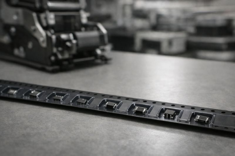
Step 1: Understand Your Component Requirements
Carrier tape selection always starts with the component itself—not with material, cost, or what was used last time. Every component brings a unique set of physical and functional constraints, and the role of the carrier tape is to manage those constraints consistently throughout feeding and placement.
Component Size & Geometry
Simple, symmetric components with flat bottoms are generally easy to support. Problems arise with irregular geometries: asymmetric bodies, uneven mass distribution, protruding leads, or delicate features. These often require deeper pockets, stepped pocket floors, or localized support points to prevent rotation, tilting, or edge contact. A pocket that merely “fits” the component is not enough—geometry determines how the part sits, aligns, and exits the pocket under motion.
Component Weight & Stability
Very small and lightweight components introduce a different risk profile. At higher feeder speeds, insufficient retention can lead to component hopping, shifting, or orientation loss inside the pocket. Heavier components, on the other hand, demand stronger pocket rigidity to avoid deformation that compromises pick-up repeatability. The tape must balance retention force with reliable release.
Component Sensitivity
Some components impose non-negotiable requirements. ESD-sensitive devices need materials and handling assumptions that minimize charge buildup. Optical components—such as LEDs or parts with exposed lenses—require pocket designs that avoid contact with critical surfaces entirely. In these cases, carrier tape is part of the protection system, not just a transport medium.
Before considering SMT line conditions or tape materials, engineers should fully define component geometry, mass behavior, and sensitivity. This foundation determines every downstream carrier tape decision.
Step 2: Define Your SMT Process Conditions
After the component is clearly understood, the next critical step is defining the actual SMT process conditions. This is where many selection guides become vague—but in practice, process parameters often matter more than the component itself. A carrier tape that performs well in one SMT environment can become unstable in another.
SMT Line Speed
Line speed fundamentally changes how a carrier tape behaves. At lower speeds, the tape experiences minimal dynamic stress, and feeding tends to be forgiving. As speed increases, acceleration, deceleration, and vibration intensify. Lightweight components may begin to shift, while marginal pocket rigidity can lead to cumulative misalignment. High-speed feeders amplify any weakness in pocket consistency, retention balance, or tape flatness.
Placement Accuracy & Tolerance Sensitivity
Modern SMT relies on tight placement tolerances, where small positional errors can cascade into rejects. Pitch accuracy plays a central role here. Even minor pitch deviations can accumulate over multiple pockets, forcing the placement system to compensate continuously. When tolerance limits are pushed, the carrier tape becomes a contributor to placement error rather than a neutral carrier.
Feeder Type & Handling Environment
Different feeder designs impose different mechanical interactions on the tape. Standard feeders may tolerate slight dimensional variation, while high-speed or precision feeders are far less forgiving. Environmental factors—such as temperature, humidity, and electrostatic conditions—also influence tape stiffness and dimensional stability during operation.
Defining SMT speed, accuracy expectations, feeder type, and operating environment creates a realistic boundary for carrier tape selection. Without this step, even a well-designed tape can fail under real production conditions.
Step 3: Choose the Right Carrier Tape Material
Once component requirements and SMT process conditions are defined, material selection becomes a directional decision—not a spec comparison exercise. The goal is not to find the “best” material on paper, but the material that delivers sufficient stability under real operating conditions without unnecessary cost or over-engineering.
When PS Carrier Tape Is Sufficient
PS carrier tape is often suitable for cost-driven programs with simple component geometries and stable, lower-speed SMT lines. When pockets are shallow, shapes are regular, and environmental conditions are controlled, PS can provide acceptable performance. The key assumption is margin: limited acceleration forces, forgiving feeders, and processes where minor dimensional variation does not directly impact yield. Outside of these boundaries, PS quickly becomes a constraint rather than an advantage.
When PET Carrier Tape Is a Better Balance
PET carrier tape occupies the middle ground between cost and stability. It offers improved dimensional consistency and better resistance to deformation under moderate to high feeder speeds. For many production lines, PET represents a practical balance—stable enough to support consistent feeding and placement, without the higher material cost associated with premium options. PET is commonly chosen when SMT speeds increase, component tolerances tighten, or process repeatability becomes more critical.
When PC Carrier Tape Becomes Necessary
PC carrier tape is typically selected when process demands leave little room for variability. High-speed lines, tight placement tolerances, and high-value or sensitive components all push material requirements upward. PC provides superior rigidity and dimensional stability, helping maintain pocket geometry and pitch accuracy under dynamic loading. In these scenarios, the cost of material is outweighed by the cost of downtime, yield loss, or component damage.
Material choice should follow process reality. Selecting the lowest-cost option that reliably supports your SMT conditions is almost always the correct engineering decision.
Step 4: Pocket, Pitch & Dimensional Considerations
With material direction established, the focus shifts to structural details that directly govern feeding stability. Pocket design, pitch accuracy, and overall dimensional consistency are where carrier tape either supports the SMT process—or quietly undermines it.
Pocket Fit vs Retention
A common mistake is evaluating pockets only by whether the component “fits.” In practice, both extremes introduce risk. Overly tight pockets can cause release issues, inconsistent pick-up height, or component sticking during cover tape peel. Overly loose pockets allow movement, rotation, or edge contact under vibration. The correct pocket design provides controlled retention: enough to stabilize the component during feeding, yet predictable release at the pick-up point.
Pitch Accuracy & Feeding Stability
Pitch is one of the most critical—and most underestimated—parameters in carrier tape selection. Inconsistent pitch forces feeders and placement systems to continuously compensate, increasing the chance of mis-picks or placement offsets. At higher speeds, small pitch variations compound rapidly, turning marginal dimensional control into repeated stoppages or yield loss. Stable pitch is not just a dimensional spec; it is a prerequisite for reliable automation.
Width & Dimensional Consistency
Tape width, pocket-to-hole alignment, and overall dimensional uniformity determine feeder compatibility. Even when nominal dimensions meet standards, variation across the reel can introduce tracking issues or lateral drift. High-speed and precision feeders are especially sensitive to this. Consistency across the entire tape length matters more than isolated measurements.
These dimensional considerations do not replace detailed design work, but they define whether a carrier tape behaves predictably in production. Good geometry supports the process invisibly; poor geometry forces constant intervention.
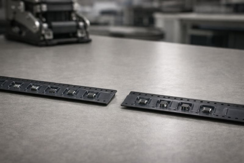
Step 5: Cover Tape Compatibility & Peel Behavior
Cover tape should never be treated as a simple sealing layer. In an SMT process, it functions as a controlled release system that directly affects pick-up reliability and placement consistency. Even a well-designed carrier tape can fail if the cover tape interaction is not properly matched.
Peel force is the key variable. If peel force is too high, components may lift, tilt, or stick to the cover tape during removal, especially at higher feeder speeds. This often results in missed picks, component rotation, or intermittent placement errors that appear random and difficult to debug. Excessive peel force can also stress delicate components or leads.
If peel force is too low, different problems emerge. Components may lose retention before the pick-up point, shift inside the pocket, or be exposed to contamination and handling damage. Low peel force can also lead to inconsistent opening behavior, where the cover tape does not separate cleanly at the intended angle or timing.
Compatibility is not just about adhesion strength. Material pairing, surface treatment, sealing method, and peel angle all influence how the cover tape behaves during feeding. Changes in line speed, temperature, or feeder setup can further alter peel behavior.
From an engineering perspective, cover tape selection must be validated together with the carrier tape—not independently. Stable peel behavior is essential for predictable pick-up, and predictable pick-up is essential for stable yield.
Step 6: Standard vs Custom Carrier Tape — How to Decide
Not every SMT project requires a custom carrier tape, but assuming standard tape is always sufficient is a common source of hidden risk. The decision should be driven by process sensitivity, not convenience.
When Standard Carrier Tape Is Enough
Standard carrier tape is usually appropriate for conventional components with well-established packaging formats and mature SMT processes. If the component geometry is simple, tolerances are forgiving, and the line operates within stable speed ranges, standard tape can deliver reliable performance. In these cases, the benefits are shorter lead times, lower upfront cost, and minimal qualification effort.
When Custom Carrier Tape Is Necessary
Custom carrier tape becomes necessary when components or processes fall outside those assumptions. Non-standard geometries, asymmetric parts, or components with exposed or sensitive features often require tailored pocket support. High-speed or high-density SMT lines amplify even small instabilities, making custom pocket geometry, tighter pitch control, or enhanced material rigidity essential for maintaining yield. For yield-critical or high-value assemblies, customization is often a risk-reduction measure rather than an optimization.
The key question is not whether custom tape is available, but whether standard tape leaves enough margin for your process. When margins shrink, customization shifts from optional to essential—long before visible failures occur in production.
Common Carrier Tape Selection Mistakes Engineers Should Avoid
Even experienced SMT engineers tend to repeat the same carrier tape selection mistakes—often because the problems only become visible after production scales. Avoiding these pitfalls is less about advanced theory and more about disciplined engineering judgment.
One common mistake is selecting carrier tape material based purely on cost. While material cost is easy to quantify, the downstream cost of feeder stoppages, mis-picks, and yield loss is not. A marginal material choice may pass early trials, only to fail when line speed increases or run time extends.
Another frequent error is ignoring changes in SMT speed or equipment. A tape that worked well on a previous line or program may become unstable when feeder acceleration, placement accuracy, or takt time changes. Reusing legacy packaging assumptions without revalidation creates unnecessary risk.
Pocket evaluation is also often oversimplified. Engineers may focus on whether the component fits inside the pocket, without considering retention behavior, orientation stability, or release consistency. This leads to subtle but persistent feeding issues.
Finally, cover tape effects are commonly underestimated. Peel behavior is treated as a secondary detail, even though incompatible cover tape is a known cause of pick-up failures and component disturbance.
Most carrier tape problems are predictable. They arise not from lack of data, but from overlooking how packaging interacts with the SMT process as a system.
A Practical Carrier Tape Selection Workflow (Engineering Summary)
Carrier tape selection becomes predictable when it follows a structured engineering sequence instead of isolated parameter checks. The objective is to remove guesswork and align packaging decisions with real SMT conditions.
1. Analyze Component Geometry and Risk
Start with the component. Define body shape, mass distribution, fragile features, and orientation sensitivity. Identify whether retention, support, or surface protection is the primary concern.
2. Define SMT Operating Conditions
Document actual line speed, feeder type, placement tolerance, and environmental factors. Avoid theoretical assumptions—use real production parameters.
3. Establish Stability Margin Requirements
Determine how much dimensional and retention margin the process needs. High-speed or yield-sensitive lines require tighter control boundaries.
4. Select Material Direction
Choose the lowest-complexity material that reliably meets the defined stability margin. Avoid over-specifying or under-specifying based on habit.
5. Validate Pocket, Pitch, and Release Behavior
Confirm retention balance, pitch consistency, and cover tape peel performance under real feeding speed.
When followed systematically, this workflow turns carrier tape selection into a controlled engineering decision rather than a reactive troubleshooting exercise.
Summary: Selecting Carrier Tape as an Engineering Decision
Carrier tape selection is a systems engineering decision, not a packaging preference. It sits at the intersection of component behavior, SMT process conditions, feeder dynamics, and yield requirements. When these factors are evaluated together, the carrier tape becomes an invisible enabler of stable production rather than a recurring source of issues.
There is no universally “best” carrier tape. The right choice is the one that provides enough mechanical and dimensional stability for your specific process, without introducing unnecessary cost or complexity. When selection is done correctly, feeding becomes predictable, placement remains consistent, and yield stays stable as volumes scale.
Treating carrier tape as part of the SMT process—not a downstream detail—allows engineers to prevent problems before they appear and maintain control as production demands increase.



 Emial
Emial John Mr


