








Carrier Tape Calculator: Pitch, Pocket & Rotation Calculation Guide
What Is a Carrier Tape Calculator?
A Carrier Tape Calculator is an engineering tool used to determine the correct pocket layout, pitch alignment, and rotation tolerance of components inside embossed carrier tape. Rather than relying on visual estimation, it applies logical relationships between component dimensions, pocket geometry, and indexing structure to ensure stable SMT feeding performance.
In practical terms, the calculator helps engineers verify whether pocket center spacing matches the required pitch structure, whether component clearance is properly controlled, and whether potential rotation stays within acceptable limits. These calculations directly influence feeder stability, pick-up accuracy, and placement consistency.
It is closely related to topics such as Carrier Tape Pitch and the broader Carrier Tape Design Guide, where structural rules and layout principles are defined.
Why Calculation Matters in SMT Packaging
In SMT packaging, small geometric deviations can translate into measurable yield loss. Carrier tape calculation is not a theoretical exercise—it directly affects pick & place stability and long-term production consistency.
If pocket centers are misaligned relative to the indexing holes, the feeder advances the tape correctly, but the component position under the nozzle shifts slightly each cycle. That positional deviation can reduce pick-up margin, increase vision correction load, or in extreme cases cause mis-picks.
Rotation error is even more sensitive. When excessive clearance exists between the component and pocket walls, micro-rotation occurs during transport or feeder acceleration. Although each rotation may appear minor, accumulated angular variation reduces suction alignment consistency. Over time, this increases placement offset and process variability.
Pitch deviation also impacts feeder synchronization. If pocket pitch does not logically align with standard index progression, tension distribution changes and feeding smoothness degrades.
This is not just a design tolerance issue—it is a yield issue. Stable SMT output depends on calculated, controlled geometry rather than assumed compatibility.
Carrier Tape Pitch Calculation Explained
Carrier tape pitch defines the center-to-center distance between adjacent pockets along the tape’s feeding direction. It determines how components are indexed by the feeder and positioned under the pick-up nozzle. While pitch is standardized around a base increment system, correct calculation requires logical alignment between pocket centers and indexing holes—not just selecting a nominal value.
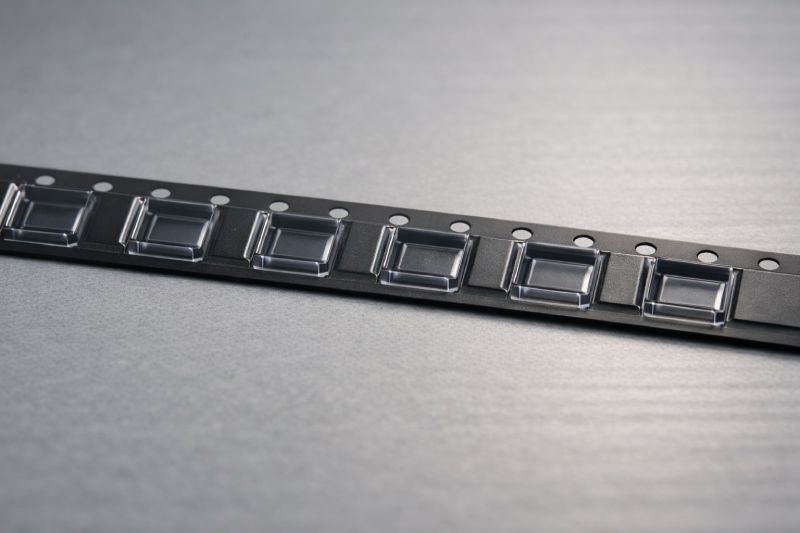
In practical design, pitch must synchronize with the indexing hole progression so that each feeder step positions the next pocket precisely under the nozzle. The relationship follows the logic defined in EIA-481: pocket centers are arranged in fixed multiples of a standard base pitch (commonly 4 mm). This ensures mechanical compatibility with SMT feeders.
Pitch calculation is therefore not an arbitrary spacing decision. It is a structural alignment exercise—matching pocket geometry, hole indexing, and feeder advancement into one coordinated system.
Basic Pitch Calculation Formula
The logical structure is:
Pocket center distance = n × standard pitch base unit
Where:
-
n represents an integer multiple
-
The base unit corresponds to the standard indexing increment
For example, if a component requires larger pocket spacing due to width or orientation, the designer increases the multiple rather than introducing a non-standard interval. This preserves feeder synchronization and structural integrity.
Common Pitch Calculation Mistakes
Two frequent engineering errors occur:
-
Confusing pocket pitch with hole pitch.
The indexing hole spacing governs feeder advancement, while pocket pitch must align with that progression—not replace it. -
Ignoring tolerance accumulation.
Even minor deviations in forming or material shrinkage can compound across multiple pockets, leading to progressive misalignment.
Accurate pitch calculation ensures repeatable indexing, stable feeding, and consistent pick position control.
How to Calculate Carrier Tape Pocket Size
Pocket size calculation defines how securely a component is seated while still allowing smooth pick-up. The objective is not to minimize clearance to zero, but to balance mechanical retention, rotation control, and suction accessibility.
The starting point is the component’s length, width, and height. These dimensions establish the minimum geometric envelope. However, pocket design must also incorporate engineering clearance to compensate for component tolerance, placement accuracy variation, and dynamic forces during transportation and feeding.
Side wall geometry and bottom support structure further influence the effective seating condition. A pocket that is too tight increases insertion stress and risk of jamming. A pocket that is too loose allows lateral movement and rotation. Therefore, calculation focuses on controlled clearance rather than simple dimensional matching.
Proper pocket sizing ensures components remain stable during transport, aligned during feeding, and accessible during pick-up.
AO / BO / KO Parameters Explained
In carrier tape drawings, three core parameters define pocket dimensions:
-
AO = pocket width (across the tape)
-
BO = pocket length (along the tape direction)
-
KO = pocket depth
Together, AO and BO define lateral clearance, while KO controls vertical stability and component exposure height.
Pocket Clearance Calculation Logic
The engineering logic can be expressed as:
Pocket size = Component dimension + Engineering clearance
Clearance is influenced by:
-
Component dimensional tolerance
-
Pick & place positioning accuracy
-
Vibration during transport and feeder acceleration
The goal is controlled movement—not free movement. Proper calculation limits rotation while maintaining reliable release during pick-up.
How to Calculate Component Rotation in Carrier Tape
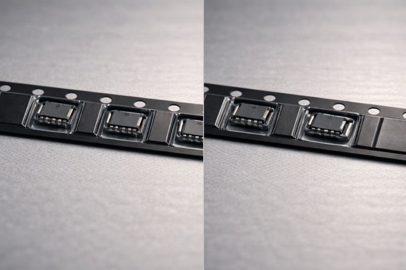
Component rotation inside the pocket refers to the angular movement allowed between the component body and the pocket side walls. While slight rotation is unavoidable due to clearance, excessive angular freedom directly affects pick-up consistency and placement accuracy.
Rotation is primarily influenced by the relationship between component dimensions and pocket geometry. When lateral clearance increases, the component gains rotational freedom. The pocket’s internal shape—rectangular, corner-relieved, or rib-supported—also affects how rotation develops during vibration and feeder acceleration.
To evaluate rotation risk, engineers examine the clearance ratio between component size and pocket size. Larger clearance relative to component width increases potential angular displacement. Conversely, controlled wall support and optimized geometry reduce rotational amplitude.
Rotation calculation is therefore a stability assessment. It determines whether the component remains predictably oriented when presented to the nozzle.
Maximum Allowable Rotation (Conceptual Formula)
A simplified engineering logic can be expressed as:
Rotation angle ∝ Clearance ratio × Pocket geometry factor
Where:
-
Clearance ratio reflects the gap between component and pocket walls
-
Pocket geometry factor reflects internal support design and corner structure
As clearance increases, allowable rotation increases proportionally.
Why Excess Rotation Causes SMT Feeding Failure
Excessive rotation impacts multiple SMT stages:
-
Suction misalignment: The nozzle may not land centrally on the component.
-
Placement shift: Angular deviation translates into XY placement offset.
-
Vision correction failure: Extreme angles exceed correction capability, increasing reject rate.
Rotation control is therefore not cosmetic—it directly influences pick success rate, alignment precision, and final yield stability.
How Pitch, Pocket & Rotation Work Together
Pitch, pocket size, and rotation tolerance are not independent variables. They form an interdependent mechanical system that determines feeding stability and placement consistency.
Pitch defines how accurately each pocket is presented to the pick position. Pocket size determines how securely the component is constrained. Rotation reflects the dynamic behavior allowed within that constraint. If one parameter shifts, the others are immediately affected.
For example, increasing pocket clearance to improve insertion tolerance may unintentionally increase rotational freedom. That added rotation interacts with pitch indexing—meaning even if pitch alignment is correct, the component may not be centered when it reaches the nozzle. Similarly, minor pitch deviation can amplify the effect of rotational variation over repeated feeder cycles.
Tolerance accumulation is the hidden risk. Small deviations in pocket forming, material elasticity, and indexing precision combine across multiple cycles. The result is not a single error, but a compounded positional shift.
In engineering terms:
Rotation stability = Controlled clearance × Accurate pitch synchronization
True SMT stability comes from coordinated design, not isolated parameter optimization.
Example Calculation Scenario (Step-by-Step Logic)
Consider a small IC component intended for high-speed SMT placement. The goal is to design a carrier tape pocket that ensures stable feeding while maintaining reliable pick-up performance.
Step 1 – Define Component Envelope
Begin by identifying the component’s nominal length, width, and height, including dimensional tolerances. This defines the minimum geometric boundary the pocket must accommodate.
Step 2 – Determine Pitch Structure
Select a pitch multiple that aligns with standard indexing progression. The pocket center spacing must logically synchronize with the indexing holes to ensure precise feeder advancement.
Step 3 – Establish Pocket Dimensions (AO / BO / KO)
Apply the clearance logic:
Pocket dimension = Component dimension + Controlled engineering clearance
Clearance is determined based on component tolerance range, feeder acceleration, and expected transport vibration.
Step 4 – Evaluate Rotation Risk
Assess the clearance ratio relative to component width. Verify that the estimated angular movement remains within acceptable limits for stable suction alignment.
Step 5 – Cross-Check Interaction
Confirm that pitch alignment, pocket size, and rotation tolerance work as an integrated system.
The calculation sequence always follows this order:
Envelope → Pitch → Pocket → Rotation → Interaction verification.
This structured logic prevents downstream feeding instability.
Calculation vs EIA-481 Standard Requirements
EIA-481 provides dimensional definitions, structural rules, and allowable tolerance ranges for carrier tape packaging. These requirements establish mechanical compatibility between carrier tape, cover tape, and SMT feeder systems. They define acceptable pitch spacing, indexing hole position, and pocket dimension boundaries (AO, BO, KO) to ensure interoperability across equipment platforms.
However, standard tolerance ranges represent permissible limits rather than application-specific optimization criteria. Within those ranges, multiple compliant design variations may exist.
In practical SMT environments, process conditions such as feeder speed, component geometry, and vibration levels can influence how dimensional variation affects feeding stability. As a result, engineers often perform additional calculation and verification beyond basic compliance checks.
Reference documentation such as Carrier Tape Specifications & EIA-481 outlines structural requirements. Engineering calculation complements these standards by helping designers evaluate dimensional relationships under real production conditions.
When Standard Calculations Are Not Enough
Standard pitch and pocket calculations work well for conventional components and moderate SMT speeds. However, certain applications require deeper engineering evaluation beyond baseline formulas.
Complex component geometry is one example. Irregular outlines, asymmetrical bodies, or uneven mass distribution increase rotation sensitivity. In such cases, standard clearance logic may technically fit the component but fail to control dynamic behavior during feeder acceleration.
High-speed SMT production is another critical scenario. As feeder indexing speed increases, vibration and inertial forces amplify. Clearance that appears acceptable at low speed may produce excessive micro-rotation under rapid advancement.
Yield-critical projects—such as automotive, medical, or high-reliability electronics—also demand tighter control. Here, minimizing angular deviation and positional drift is more important than simply meeting dimensional tolerance ranges.
In these situations, engineers often require a Custom Carrier Tape solution or a fully optimized Custom Embossed Carrier Tape design.
When rotation stability, pitch synchronization, and pocket geometry must work within narrow process margins, tailored calculation becomes necessary—not optional.
Summary: Engineering Accuracy Drives SMT Stability
Carrier tape calculation is a preventive engineering process—not a corrective action after feeding problems appear. Pitch alignment ensures consistent indexing. Pocket sizing controls component stability. Rotation evaluation protects pick-up accuracy. These three parameters must be calculated as an integrated system rather than optimized individually.
Small geometric assumptions can translate into measurable yield loss in high-speed SMT environments. Accurate design reduces vibration-induced movement, minimizes angular deviation, and stabilizes placement performance.
In practice, engineering precision at the packaging stage is far more effective than troubleshooting instability during production.



 Emial
Emial John Mr


