








How to Measure Carrier Tape Dimensions Correctly for SMT
Why Accurate Carrier Tape Measurement Matters in SMT
Accurate carrier tape measurement is not a routine inspection task — it is a critical control point in SMT production stability. Even small dimensional deviations can directly affect feeding accuracy, component positioning, and long-term yield performance.
In automated assembly lines, feeders rely on consistent tape width, pitch spacing, and sprocket hole alignment to advance components precisely. If dimensions drift outside functional limits, components may shift inside pockets, rotate during indexing, or fail to present correctly to the pick-and-place nozzle. These issues often lead to misplacement, tombstoning, or machine stoppages.
Measurement also ensures compatibility between carrier tape and feeder systems. Different feeders have strict mechanical tolerances, and poor dimensional control can create intermittent indexing errors that are difficult to trace.
For deeper structural background, see the Carrier Tape Design Guide and Carrier Tape Pitch Explained, which explain how these dimensions are defined during engineering design.
Key Carrier Tape Dimensions You Must Measure
Precise carrier tape evaluation requires systematic measurement of several critical structural dimensions. Each parameter directly influences feeding stability and component protection during SMT processing.
-
Tape width – Ensures mechanical compatibility with feeder tracks and guide rails. Incorrect width can cause lateral instability or feeding resistance.
-
Pocket width and pocket length – Determine how securely the component sits inside the embossed cavity. Excess clearance increases rotation risk; insufficient clearance may cause mechanical stress or component damage.
-
Pocket depth – Controls vertical retention and pick-up reliability. If depth is incorrect, components may tilt, float, or fail vacuum pick-up.
-
Pitch (pocket-to-pocket distance) – Governs indexing synchronization between sprocket holes and pocket positions. Pitch variation can lead to cumulative feeding misalignment.
-
Sprocket hole (D1) position – Critical for feeder indexing accuracy. Hole-to-pocket positional accuracy determines whether the pick head aligns correctly with each component.
-
Cover tape sealing area – Ensures secure sealing without interfering with pocket geometry. Insufficient sealing width may cause peel instability during feeding.
For a structural breakdown of these parameters, refer to Carrier Tape Dimensions, Carrier Tape D1 Hole, and Carrier Tape Pitch for detailed technical explanations.
Tools Required to Measure Carrier Tape Dimensions
Accurate carrier tape measurement depends not only on what you measure, but also on how you measure it. Selecting appropriate tools ensures dimensional data reflects real engineering conditions rather than distorted readings.
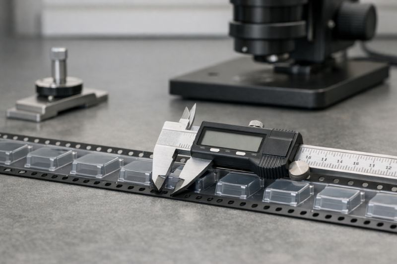
Digital caliper – Suitable for measuring overall tape width, pocket opening dimensions, and basic structural distances. It provides fast and repeatable measurements, but care must be taken to avoid compressing embossed areas during contact.
Optical microscope or profile projector – Used for non-contact inspection of pocket geometry, sprocket hole alignment, and pitch consistency. Optical systems reduce deformation risk and improve measurement accuracy for small components.
Depth gauge – Essential for measuring pocket depth without collapsing the embossed structure. A flat, stable base ensures vertical measurement consistency.
Measuring microscope (high-precision applications) – Recommended when tight tolerances or micro-components are involved. It allows accurate evaluation of hole-to-pocket positional relationships and detailed geometry verification.
Tool selection should match the precision level required by the application. For general feeder compatibility checks, calipers may be sufficient. For validation or first-article approval, optical and precision instruments are strongly recommended to avoid measurement-induced error.
Step-by-Step: How to Measure Carrier Tape Correctly
Accurate carrier tape measurement requires a controlled, repeatable process. Random checks or inconsistent technique can produce misleading data and incorrect engineering conclusions. The following method reflects practical SMT validation procedures.
Step 1: Confirm Tape Orientation
Before any measurement, verify tape orientation. Identify the sprocket hole side and confirm pocket direction relative to feeding flow. Measuring from the wrong edge or reversing reference direction can invalidate hole-to-pocket positional readings. Always define a consistent datum edge — typically the sprocket hole side — before recording dimensions.
Step 2: Measure Overall Tape Width
Place the tape flat on a stable surface without tension or curl. Use a digital caliper to measure the overall width across multiple sections. Avoid excessive clamping pressure, as carrier tape materials can flex slightly under force. Measure at several points along the tape length to confirm dimensional consistency.
Step 3: Measure Pocket Dimensions
When measuring pocket width and length, do not compress the embossed cavity. Apply minimal contact force if using a caliper. For higher precision, use optical inspection to capture the true pocket opening geometry. If measuring depth, use a depth gauge carefully positioned to avoid collapsing the pocket floor.
Step 4: Measure Pitch Distance
Measure the distance between consecutive pocket centers or corresponding sprocket holes. Do not rely on a single measurement point. Instead, measure across multiple pockets and calculate the average value. This helps detect cumulative pitch deviation that may not be visible from one interval alone.
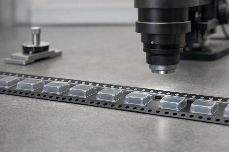
Step 5: Measure Sprocket Hole Position
Verify the positional relationship between sprocket holes and pocket centers. This measurement directly affects feeder indexing accuracy. Use optical tools when possible to reduce alignment error. Multiple samples should be checked to ensure positional stability across the tape length.
Following this structured process ensures that carrier tape dimensions reflect functional performance rather than isolated measurement points.
Common Mistakes When Measuring Carrier Tape
Even experienced engineers can introduce measurement errors if proper procedures are not followed. Many SMT feeding problems originate not from tape design itself, but from inaccurate or incomplete dimensional verification.
One common mistake is measuring only a single pocket. Carrier tape is produced in continuous lengths, and dimensional variation can occur gradually. Relying on one measurement point ignores potential pitch drift or tolerance accumulation along the reel.
Another frequent error is applying excessive pressure to the embossed area. Carrier tapes made from PS, PET, or PC materials can flex slightly under force. Compressing the pocket during measurement produces artificially reduced width or depth values, leading to incorrect engineering conclusions.
Engineers also often ignore tolerance stacking effects. Measuring each parameter individually without considering cumulative deviation may hide functional misalignment between sprocket holes and pocket centers.
Finally, failing to check multiple samples or production batches can mask process instability. First-article approval alone does not guarantee long-term consistency.
Avoiding these mistakes ensures that measurement data reflects real-world feeding behavior, not inspection artifacts.
Tolerance Considerations in Carrier Tape Measurement
Measuring carrier tape dimensions is not only about confirming nominal values. Engineering evaluation must focus on how dimensions function within allowable tolerance ranges under real SMT operating conditions.
First, it is important to distinguish between nominal dimensions and functional dimensions. A nominal value represents the intended design target, but functional performance depends on whether the dimension remains stable within its tolerance band during feeding and pick-up. A pocket may meet nominal width yet still allow excessive component rotation if it sits near the upper tolerance limit.
Second, engineers must consider the tolerance stacking effect. Small deviations in pitch, sprocket hole position, and pocket center alignment can accumulate across multiple indexing steps. While each individual deviation may appear minor, combined variation can result in misalignment between the component and pick head over time.
Measurement repeatability is another key factor. If repeated measurements of the same tape produce inconsistent results, the measurement method itself may be introducing error. Tool stability, operator technique, and environmental conditions all influence repeatability.
For structural reference and tolerance frameworks, see Carrier Tape Specifications & EIA-481 Standard. A deeper breakdown of dimensional control logic can be found in Carrier Tape Tolerance Explained, which examines how tolerances impact real feeding performance.
How Measurement Relates to EIA-481 Standards
Carrier tape measurement should always be structured around the dimensional framework defined by EIA-481. This standard establishes the mechanical layout of embossed carrier tapes used for SMT, including pitch structure, sprocket hole geometry, and tape format consistency.
When engineers measure tape width, pocket position, pitch, or hole alignment, they are not measuring randomly — they are verifying conformance to a standardized mechanical system. The relationship between sprocket holes and pocket centers, for example, is defined structurally to ensure feeder indexing accuracy across compatible equipment.
However, compliance with the standard does not automatically guarantee perfect feeding performance. The standard defines structural boundaries, not application-specific optimization. Factors such as component mass, pocket clearance strategy, and feeder mechanics may require tighter internal control than the baseline specification.
When Measurement Indicates a Design Problem
Dimensional measurement is not only a verification step — it is also a diagnostic tool. When measured values approach functional limits or show inconsistent variation, they may indicate an underlying carrier tape design issue rather than simple production fluctuation.
For example, if pocket width measurements consistently show excessive clearance relative to component size, this increases the risk of micro-rotation during indexing. Even if nominal dimensions are technically within tolerance, the functional outcome may be unstable component orientation during pick-up.
If pitch measurements reveal deviation across multiple intervals, this can lead to feeding instability. Small pitch variation may accumulate over several indexing steps, eventually causing the pick head to miss the component center.
Similarly, misalignment between sprocket holes and pocket centers often signals tooling or forming inconsistency. Because feeders index based on hole position, even slight positional shift can create repeated placement offset.
Measurement results should therefore be interpreted in context. Instead of asking “Is it within nominal tolerance?”, engineers should ask “Does this dimensional behavior support stable feeding?”
For deeper structural evaluation logic, see the Carrier Tape Design Guide and Custom Carrier Tape, which explain how design adjustments can correct functional instability revealed through measurement.
How Often Should Carrier Tape Be Measured in Production?
Carrier tape measurement should be treated as a controlled production activity rather than a one-time inspection task. Measurement frequency depends on process stability, material type, and application sensitivity.
At minimum, first article validation is required whenever a new design, tooling adjustment, or material change is introduced. This ensures that pocket geometry, pitch, and sprocket hole position meet functional expectations before mass production begins.
During production, batch sampling should be implemented at defined intervals. Random sampling across different reel sections helps detect gradual pitch drift, forming variation, or hole misalignment that may not appear at the beginning of the run.
For stable processes with established capability, periodic process stability checks are sufficient. However, for tight-tolerance semiconductor components or high-speed SMT lines, more frequent measurement is recommended to prevent cumulative feeding deviation.
From a manufacturing perspective, consistent measurement is not excessive control — it is preventive risk management that protects downstream SMT yield and equipment reliability.
Summary: Measuring Carrier Tape as an Engineering Control Step
Carrier tape measurement is not administrative paperwork — it is a core engineering control step in SMT production. By verifying tape width, pocket geometry, pitch stability, and sprocket hole alignment, engineers protect feeding accuracy and component positioning reliability.
Structured measurement prevents cumulative tolerance errors, reduces feeder-related downtime, and supports consistent yield performance. When integrated into first-article validation and routine process checks, dimensional verification becomes a proactive stability tool rather than a reactive troubleshooting step.
Ultimately, accurate measurement ensures that carrier tape functions as intended within standardized frameworks while meeting real-world SMT performance demands.



 Emial
Emial John Mr


