








Carrier Tape Tolerance Explained | Why Small Deviations Impact SMT Accuracy
What Is Carrier Tape Tolerance?
Carrier tape tolerance refers to the allowable dimensional variation in embossed or formed tape features without disrupting automated SMT performance. It does not simply describe a fixed number taken from a specification table. Instead, tolerance defines the controlled range within which a feature can vary while still maintaining reliable feeder indexing and pick-and-place stability.
Every carrier tape dimension has two parts:
-
Nominal dimension — the intended target size in design
-
Allowable deviation — the acceptable variation around that target
In tape & reel packaging systems, tolerance is not an isolated measurement parameter. It functions as a system parameter, because pocket geometry, pitch alignment, sprocket hole position, and overall width directly interact with feeder mechanics and component positioning. A deviation that appears small in isolation may influence indexing timing, pickup accuracy, or placement consistency once integrated into a high-speed SMT process.
Carrier tape tolerance defines how much a dimension may vary without affecting feeder indexing and pick-and-place stability.
For a deeper understanding of structural parameters, see Carrier Tape Specifications and Carrier Tape Dimensions.
Where Tolerances Exist in Carrier Tape Design
Carrier tape tolerance is distributed across multiple structural features. These features do not operate independently; each one influences how the tape feeds, indexes, and presents components during SMT assembly. Understanding where tolerances exist helps engineers identify potential sources of instability before they appear on the production line.
Pocket Width & Depth Tolerance
Pocket width and depth determine how securely a component is seated. If the width varies excessively, lateral clearance increases, allowing micro-rotation during feeder acceleration. If depth varies, component coplanarity and pickup height consistency may be affected. Even minor deviations can influence vacuum nozzle engagement and orientation stability.
Pitch Tolerance
Pitch defines the center-to-center distance between consecutive pockets. Variations in pitch affect how accurately each component aligns with feeder indexing steps. Small pitch deviations may accumulate over multiple pockets, leading to progressive offset between expected and actual pickup positions.
Sprocket Hole (D1) Position Tolerance
Sprocket holes control mechanical indexing. Their positional tolerance determines how precisely the feeder advances the tape. Any deviation between hole location and pocket center shifts the component presentation point, directly impacting pick accuracy.
Overall Tape Width Tolerance
Tape width tolerance influences how the tape tracks within feeder rails. Excess variation may cause lateral play or friction imbalance, reducing feeding smoothness and positional repeatability.
Together, these tolerances form an interdependent system that governs mechanical stability in automated SMT environments.
Why Tolerance Is Critical in High-Speed SMT
In high-speed SMT environments, tolerance sensitivity increases dramatically. What appears negligible in static inspection can become amplified under dynamic feeder motion.
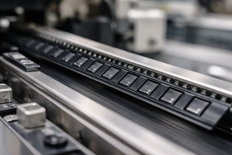
Modern feeders operate with rapid indexing cycles, sudden acceleration, and precise stop positioning. Under these conditions, dimensional deviations do not remain isolated—they interact with mechanical timing and motion inertia. A small variation in pitch or pocket alignment can shift how the tape advances relative to the pickup point.
The engineering cause-and-effect chain typically follows this pattern:
Dimension deviation
→ Indexing shift
→ Pick position offset
→ Placement accuracy reduction
At low speeds, a 0.05 mm deviation may produce no visible issue because system inertia and timing buffers absorb the error. However, at high feeder speeds, that same deviation can alter pickup centering enough to increase rotational variation or reduce placement repeatability.
The faster the line speed, the less tolerance the system has for geometric inconsistency. High-speed SMT does not merely require compliance with specification limits—it demands dimensional stability that preserves positional synchronization across every indexing cycle.
Tolerance Stack-Up: The Hidden Risk in Tape & Reel Systems
Tolerance stack-up refers to the cumulative effect of multiple dimensional variations interacting within the tape & reel system. While each individual tolerance may fall within its allowable range, their combined influence can produce a measurable positional shift.
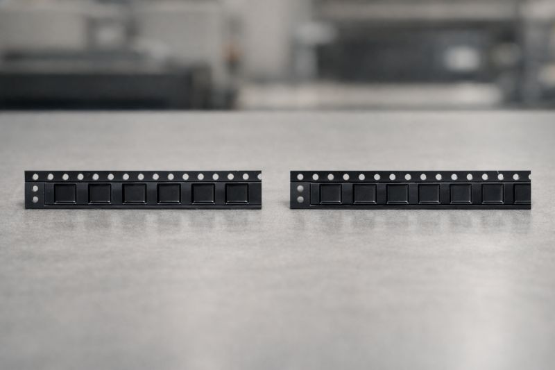
In carrier tape design, three primary contributors typically interact:
-
Pocket geometry tolerance (width and depth variation)
-
Pitch tolerance (center-to-center spacing deviation)
-
Sprocket hole position tolerance (indexing reference deviation)
Individually, these variations may appear insignificant. However, when the feeder advances pocket after pocket, small shifts can accumulate. For example, a slight pitch deviation combined with minor sprocket hole offset can gradually move the effective pickup position away from the nominal center. If pocket width tolerance simultaneously allows additional lateral play, the component may no longer present consistently under the nozzle.
This is not a single-point defect. It is a systemic offset created by interacting tolerances. The result may be progressive misalignment rather than an immediate failure, making it more difficult to diagnose.
Most performance issues attributed to “feeder instability” are, in reality, tolerance stack-up effects within the tape & reel geometry. Understanding this interaction is essential for preventing hidden positional drift in high-speed SMT production.
Manufacturing Reality: Why Perfect Tolerance Does Not Exist
In practical manufacturing, perfect dimensional consistency is not physically achievable. Tolerance does not represent absolute precision—it represents controlled capability within defined process limits.
Carrier tape is typically formed through thermoforming or embossing processes. During forming, material behavior introduces variability. Polymer sheets expand and contract with temperature changes. Cooling rates influence shrinkage patterns. Even minor fluctuations in raw material batches can affect stiffness, elasticity, and forming response.
Tooling condition also plays a role. Mold wear, surface micro-abrasion, and long production cycles gradually influence pocket geometry. These variations do not indicate poor quality control; they reflect the mechanical realities of continuous manufacturing.
Environmental factors further contribute. Ambient temperature and humidity can alter material dimensional stability before and after forming. As a result, tolerance is a measure of how consistently a manufacturer can control variation—not a guarantee of mathematical perfection.
Understanding this reality shifts the perspective from “zero deviation” to “process control capability.” In SMT applications, the goal is not eliminating variation entirely, but ensuring that variation remains predictable and compatible with system-level requirements.
Tolerance vs Fit: Why Passing Spec Is Not Always Enough
Meeting specification limits does not automatically guarantee optimal SMT performance. A carrier tape can comply with industry standards such as EIA-481 and still create instability under real production conditions.
Tolerance defines allowable variation in the tape. Fit describes how the actual component interacts with the pocket under dynamic feeder motion. These are related—but not identical—concepts.
For example, a pocket width that falls within specification may still provide excessive lateral clearance if the component itself trends toward the lower end of its own dimensional range. Conversely, if the component size trends larger, even a nominally compliant pocket may introduce insertion stress or vertical instability.
Feeder brand and mechanical design further influence real-world behavior. Different feeder systems apply different clamping forces, indexing dynamics, and stop accuracy. A tolerance range that performs well on one platform may show higher rotation or offset on another.
Therefore, compliance with specification is a baseline requirement—not an engineering guarantee. Optimal performance requires evaluating how tape tolerance interacts with component variation and feeder mechanics within the actual production environment.
How to Evaluate Carrier Tape Tolerance in Your Project
Evaluating carrier tape tolerance should be based on production conditions rather than specification tables alone. The critical factor is how dimensional variation interacts with your SMT operating parameters.
If SMT speed is relatively low, feeder acceleration forces are reduced and indexing timing is less aggressive. In such environments, minor dimensional deviations are less likely to amplify into pickup instability. Tolerance risk exists, but the system may naturally absorb small variations.
If SMT speed is high, tolerance becomes significantly more critical. Rapid indexing reduces the system’s ability to compensate for positional drift. Even small pitch or hole alignment deviations can shift pickup centering. In high-speed lines, tighter tolerance control directly supports placement consistency.
If the component has tight coplanarity or strict orientation requirements, pocket tolerance must be carefully controlled. Components with minimal allowable rotation or height variation are more sensitive to lateral clearance and depth variation.
The evaluation logic is therefore conditional:
-
Higher speed → higher tolerance sensitivity
-
Higher component precision → stricter pocket control required
-
More stable process → lower tolerance risk
Carrier tape tolerance should always be assessed relative to system dynamics, not in isolation.
Common Tolerance-Related Problems in SMT
Tolerance-related issues in SMT often appear as mechanical or feeder faults, but many originate from dimensional variation within the tape & reel system.
One common symptom is component rotation. Excess lateral pocket clearance combined with pitch deviation can allow slight angular movement during indexing. Under high acceleration, this micro-rotation becomes visible at pickup.
Another issue is pick misalignment. When sprocket hole position tolerance interacts with pitch variation, the actual pickup center may shift relative to the programmed nozzle position. The result is off-center vacuum engagement or inconsistent pickup height.
Feeder skipping can also be linked to tolerance interaction. Variations in hole geometry or tape width may affect indexing smoothness, especially in high-speed feeders that rely on precise mechanical engagement.
Finally, inconsistent placement accuracy may occur even when individual components pass inspection. This often indicates cumulative tolerance stack-up rather than a calibration problem.
Importantly, these symptoms are frequently misdiagnosed as feeder instability or machine error. In many cases, the underlying cause is the combined effect of pocket, pitch, and hole tolerances interacting within dynamic SMT conditions.
Tolerance Considerations in Custom Carrier Tape Design
When components fall outside standard size categories, tolerance evaluation must be reassessed from the beginning. Non-standard geometries, asymmetric bodies, or tight coplanarity requirements increase sensitivity to pocket variation and indexing alignment.
In custom projects, tolerance is not simply inherited from a general specification. Pocket width, depth, pitch alignment, and hole positioning must be reviewed relative to the specific component’s dimensional spread. A design that works for one device may not provide the same stability for another with different weight distribution or lead structure.
Prototype sampling and feeder validation are therefore essential. Trial runs reveal whether lateral clearance, vertical seating depth, or indexing synchronization introduce micro-instability under real operating speeds. Early validation reduces downstream risk.
Material selection also influences tolerance behavior. For example, rigidity differences between PC Carrier Tape and PS Carrier Tape affect forming precision and dimensional stability over temperature variation. Selecting the appropriate material becomes part of tolerance control strategy.
For engineered solutions tailored to specific components, see Custom Carrier Tape. In custom design, tolerance is not a default parameter—it is a controlled engineering decision.
Summary: Tolerance as a System-Level Parameter
Carrier tape tolerance is not an isolated dimensional allowance—it is a system-level variable that directly influences feeder synchronization, pickup stability, and placement accuracy.
In high-speed SMT environments, small deviations can amplify through indexing cycles, creating measurable positional drift. When pocket geometry, pitch alignment, and sprocket hole position interact, tolerance stack-up becomes a hidden but critical risk factor.
Effective tape design therefore requires more than passing specification limits. Engineers must evaluate tolerance in relation to component variation, feeder mechanics, production speed, and material behavior.
At the design stage, controlling tolerance means controlling system stability. In modern SMT assembly, dimensional variation is never neutral—it either supports precision or gradually erodes it.



 Emial
Emial John Mr


