








Carrier Tape Feeding Problems: Causes, Symptoms & Engineering Solutions
What Are Carrier Tape Feeding Problems?
Carrier tape feeding problems refer to abnormal tape movement or indexing behavior during the SMT (Surface Mount Technology) assembly process. In a properly functioning system, the carrier tape advances precisely by one pitch at each indexing cycle, presents the component at a fixed and repeatable pick position, and maintains stable alignment with the feeder mechanism. When this controlled progression fails, feeding problems occur.
In practical production environments, these issues often manifest as indexing errors, feeder skipping, inconsistent pick positions, component mispicks, or subtle tape drift. Operators may also observe unexpected component rotation inside the pocket, partial presentation, or intermittent placement accuracy degradation. In some cases, the tape appears to move, but not in exact pitch increments, leading to cumulative positioning shifts over time.
Carrier tape feeding problems occur when the tape fails to advance, index, or present components consistently to the pick-and-place system.
Importantly, feeding problems are not limited to complete stoppage or obvious mechanical jams. Even small deviations in pitch accuracy, sprocket hole engagement, cover tape peel behavior, or pocket retention can disrupt stable indexing. Because SMT systems operate on tight positional tolerances, especially at high speeds, even minor feeding inconsistencies can translate into reduced placement accuracy, increased machine alarms, or yield loss.
Understanding what qualifies as a feeding problem is the first step toward diagnosing its engineering root causes.
How Carrier Tape Feeding Works in SMT Systems
To understand feeding problems, it is essential to first understand how carrier tape feeding is designed to function within an SMT system. Feeding stability is not accidental — it is the result of coordinated mechanical indexing, dimensional control, and material behavior working together.
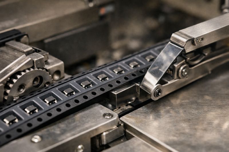
At the core of the system is the feeder indexing mechanism. The feeder uses a sprocket-driven advancement system that engages precisely with the tape’s sprocket holes (commonly referred to as D1 holes). Each indexing cycle advances the tape forward by exactly one pitch. The pitch progression must remain consistent across the entire reel, because the pick-and-place machine assumes that every pocket center advances in fixed increments.
Sprocket hole engagement is critical. The position, diameter, and roundness of the D1 holes determine how accurately the feeder can grip and advance the tape. Even small positional deviations can create micro-slippage, progressive indexing shift, or inconsistent stop positions.
Simultaneously, cover tape peeling must be synchronized with indexing. As the tape advances, the cover tape is peeled back at a controlled angle and force. The peel force must remain within a stable range: too high and it increases tension resistance during indexing; too low and it may cause premature component movement or incomplete sealing integrity before peeling.
Finally, the pocket geometry determines how the component is presented after cover tape removal. The pocket must retain the component securely during transport while still allowing reliable vacuum pick-up. Clearance, pocket depth, and centering accuracy all influence presentation consistency.
In short, carrier tape feeding is a coordinated mechanical system based on:
-
Controlled pitch progression
-
Precise sprocket hole engagement
-
Stable cover tape peel behavior
-
Accurate pocket design and component positioning
When any one of these parameters drifts beyond acceptable tolerance, feeding instability can begin — even if the deviation appears minor at first glance.
Common Symptoms of Carrier Tape Feeding Problems
Before identifying root causes, engineers must first recognize the observable symptoms. Carrier tape feeding problems often present as production inconsistencies rather than obvious mechanical failures. In many cases, the feeder continues operating, but performance gradually degrades.
One of the most common symptoms is feeder skipping steps. The tape may advance irregularly or fail to index exactly one pitch per cycle. This can trigger feeder alarms or, more subtly, shift the component pick position over time.
Component misalignment is another frequent indicator. Even when the tape advances, the component may not appear centered under the nozzle. Slight pitch deviation or sprocket engagement instability can cause the pocket center to drift relative to the programmed pick coordinate.
Operators may also observe inconsistent pick positions. The first several picks may appear stable, but after multiple indexing cycles, the nozzle begins compensating or producing intermittent mispicks. This is often a sign of cumulative tolerance effects.
Tape drifting sideways within the feeder track is another visible symptom. Lateral instability can result from sprocket hole positioning errors, uneven peel tension, or feeder wear. Side drift may lead to inaccurate presentation or frictional resistance during indexing.
Unexpected component rotation inside the pocket is also a common issue. If pocket clearance is excessive or cover tape peel force is unstable, components may shift orientation just before pick-up, increasing placement rejection rates.
Importantly, these symptoms describe what happens — not why it happens. Recognizing the pattern of behavior allows engineers to begin structured root cause analysis rather than assuming the tape alone is at fault.
Root Causes of Carrier Tape Feeding Problems
Carrier tape feeding problems rarely originate from a single defect. In most cases, they are the result of interacting tolerances, material behavior, and equipment conditions. A structured analysis helps isolate the true engineering cause instead of assigning blame prematurely.
Below are the most common root cause categories.
Pitch Deviation & Cumulative Tolerance
Pitch accuracy is fundamental to feeding stability. Each pocket must advance forward in consistent increments equal to the nominal pitch dimension. Even small pitch deviations — well within individual tolerance limits — can accumulate over multiple indexing cycles.
This phenomenon is known as tolerance stack-up. A ±0.05 mm pitch variation may seem insignificant in a single step. However, after 20 or 30 indexing movements, the cumulative shift can exceed the pick-and-place system’s positional compensation range.
The result:
Minor pitch variation
→ incremental indexing shift
→ off-center pick position
→ increased mispick probability
Because SMT systems rely on fixed programmed coordinates, cumulative pitch error is one of the most underestimated feeding risks.
Sprocket Hole (D1) Misalignment
The D1 sprocket hole is the mechanical reference point for feeder engagement. If hole position deviates relative to pocket centerlines, indexing stability is immediately affected.
Common issues include:
-
Hole-to-pocket positional deviation
-
Inconsistent hole spacing
-
Ovality or deformation
-
Edge burrs affecting engagement
When sprocket holes are not precisely aligned, the feeder pin may engage inconsistently. This can cause micro-slippage, uneven tape advancement, or slight angular drift during progression.
Even when pitch appears acceptable, hole misalignment can produce unstable indexing because the mechanical driving reference itself is inconsistent.
Cover Tape Peel Force Issues
Cover tape behavior plays a larger role in feeding stability than many engineers expect. The peel force must remain within a controlled range during operation.
If peel force is too high:
-
Excessive tension increases feeder resistance
-
Indexing motion becomes uneven
-
Tape stretch or micro-distortion may occur
If peel force is too low:
-
Component retention before peeling may be compromised
-
Components may shift within pockets during peel
-
Presentation accuracy may decrease
Because peel tension interacts dynamically with indexing motion, unstable peel force can indirectly contribute to pitch drift or lateral movement.
Pocket Design & Clearance Problems
Pocket geometry directly affects component presentation consistency. Clearance must be carefully balanced:
-
Too tight → insertion stress, deformation risk
-
Too loose → component movement during transport
Excessive lateral clearance allows micro-rotation inside the pocket. At low speed, this may not create visible issues. At high speed, vibration and acceleration amplify component movement.
Additionally, insufficient pocket depth or poor bottom support can allow vertical rocking, leading to inconsistent vacuum engagement during pick.
Feeding stability depends not only on tape movement but also on how securely the component remains positioned until the moment of pick-up.
Tape Material Rigidity Issues
Material selection influences dimensional stability and resistance to mechanical stress.
For example:
-
PS (Polystyrene) offers cost efficiency but lower rigidity
-
PC (Polycarbonate) provides higher structural stability and deformation resistance
Under indexing stress, peel tension, and environmental variation, lower-rigidity materials may experience slight deformation. Even minimal warping or edge curl can affect feeder tracking consistency.
Material elasticity also affects long-run performance. A tape that feeds well initially may gradually exhibit drift if material recovery characteristics are insufficient.
Feeder & Equipment Factors
It is important not to attribute all feeding problems to the carrier tape itself. Equipment conditions frequently contribute to instability.
Common equipment-related factors include:
-
Feeder wear or worn sprocket pins
-
Improper feeder setup or misalignment
-
Machine tolerance limitations
-
Inconsistent peel angle configuration
-
Poor reel mounting or tension control
A worn feeder can introduce indexing backlash. Improper calibration may exaggerate otherwise minor tape deviations. Even small mechanical looseness in the feeder assembly can amplify feeding inconsistencies.
For this reason, feeding problems should always be evaluated as a system-level interaction between:
Tape design
Material behavior
Dimensional tolerance
Feeder condition
Machine setup
Only by analyzing all these elements together can engineers accurately identify the true root cause of feeding instability.
Why Feeding Problems Worsen in High-Speed SMT
Feeding problems that appear minor at low production speeds often become critical when line speed increases. This is not coincidence — it is a predictable amplification effect driven by system dynamics.
At lower SMT speeds, small dimensional deviations or slight indexing inconsistencies may remain within the machine’s positional tolerance window. The feeder has more time to stabilize between cycles, peel tension changes occur more gradually, and vibration energy is limited.
However, as production speed increases, three key amplification mechanisms occur:
First, indexing acceleration increases. The tape must advance and stop more rapidly within shorter cycle times. Any pitch deviation or sprocket engagement instability becomes more pronounced under higher acceleration forces.
Second, dynamic tension rises. Cover tape peel force interacts with faster indexing motion, increasing the likelihood of micro-stretch, resistance variation, or lateral shift.
Third, vibration energy increases. High-speed feeders generate more mechanical oscillation. If pocket clearance is marginal or material rigidity is insufficient, components may shift inside the cavity just before pick-up.
This creates a typical engineering cause-and-effect chain:
Minor pitch deviation
→ incremental indexing shift
→ reduced alignment accuracy at high acceleration
→ inconsistent pick position
→ placement accuracy reduction
In high-speed SMT environments, tolerances that are “acceptable” at low speed may no longer be stable. The system becomes less forgiving, and small dimensional or material variations translate into measurable yield impact.
For this reason, feeding stability must always be evaluated relative to intended production speed — not merely dimensional compliance on paper.
Tolerance Stack-Up: The Hidden Feeding Risk
Tolerance stack-up is one of the most overlooked contributors to carrier tape feeding instability. In many cases, every individual parameter may comply with specification — yet the system as a whole becomes unstable.
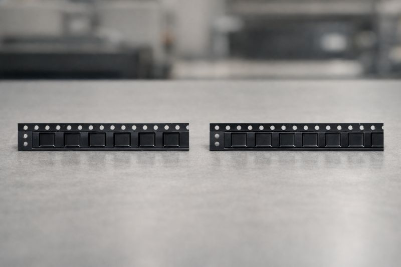
In a typical carrier tape feeding system, several tolerances interact simultaneously:
-
Pitch tolerance
-
Pocket position tolerance
-
Sprocket hole (D1) position tolerance
-
Cover tape alignment tolerance
-
Feeder mechanical tolerance
Individually, each deviation may appear minor. For example, a small pitch variation, a slight hole-to-pocket offset, and minimal feeder backlash may all fall within acceptable limits. However, when these tolerances align in the same directional bias, their combined effect can exceed the machine’s positional compensation range.
This cumulative effect explains why a tape that “meets specification” can still produce intermittent feeding errors.
Consider the interaction:
Pitch deviation shifts pocket center incrementally.
Sprocket hole offset alters indexing reference.
Feeder backlash introduces micro positional play.
Together, these factors create a compound displacement at the pick point.
The critical insight is this: single-parameter compliance does not guarantee system-level stability. Feeding reliability depends on how tolerances interact under dynamic operating conditions.
Engineers who evaluate carrier tape only by isolated dimensional checks may overlook this hidden risk. A system-based tolerance assessment — especially for high-speed SMT — is essential to prevent cumulative drift and long-run feeding instability.
How to Diagnose Carrier Tape Feeding Problems
Diagnosing carrier tape feeding problems requires structured evaluation rather than immediate replacement of components or feeders. Because feeding stability is a system-level interaction, the goal is to isolate which parameter is deviating under operating conditions.
The following diagnostic logic provides a practical evaluation framework.
1. Check Pitch Consistency
Begin by verifying pitch accuracy across multiple indexing lengths — not just a single interval. Measure cumulative pitch over 10–20 pockets to detect progressive deviation.
Key observations:
-
Is pitch variation random or directional?
-
Does deviation increase over distance?
-
Does the feeder compensate initially but drift later?
Cumulative measurement is often more revealing than single-step inspection.
2. Inspect Sprocket Hole Alignment
Evaluate D1 sprocket hole position relative to pocket centerlines. Inspect for:
-
Hole-to-pocket offset
-
Inconsistent hole spacing
-
Ovality or deformation
-
Engagement wear marks
Unstable sprocket engagement can produce indexing micro-slip even when pitch appears acceptable. If drift direction aligns with hole offset direction, this is a strong indicator of engagement instability.
3. Measure Peel Force Behavior
Peel force should be evaluated dynamically, not just statically. Observe:
-
Is peel resistance consistent across the reel?
-
Does peel tension fluctuate at higher speed?
-
Does peel angle remain stable?
Excessive peel force can increase indexing load, while insufficient peel stability may allow component disturbance during removal. Peel behavior often changes under high-speed conditions.
4. Evaluate Pocket Retention Stability
Inspect component stability within the pocket prior to pick-up:
-
Is there excessive lateral clearance?
-
Does the component rotate under light vibration?
-
Is pocket depth sufficient to prevent rocking?
If components shift just before pick, the issue may not be indexing accuracy but retention design.
5. Assess Feeder Condition
Finally, inspect the feeder itself:
-
Check sprocket pin wear
-
Verify indexing gear backlash
-
Confirm correct setup and alignment
-
Ensure reel tension is properly adjusted
Feeder wear or improper calibration can amplify minor tape deviations.
Diagnosis Principle
Do not assume the tape is defective solely because feeding instability appears. Instead:
Observe the symptom
Measure cumulative deviation
Isolate dynamic interaction
Validate against feeder condition
Feeding problems are best diagnosed through elimination of variables and systematic dimensional verification. A structured approach prevents unnecessary tape redesign while identifying genuine design-level instability when present.
Preventing Feeding Problems Through Design & Material Selection
While troubleshooting is important, the most effective way to manage carrier tape feeding problems is prevention at the design stage. Feeding stability is rarely achieved through correction alone — it is engineered through dimensional control, material selection, and application-specific design decisions.
Design for Required Precision Level
Not all applications demand the same stability margin. For lower-speed SMT lines or cost-sensitive consumer products, standard PS carrier tape with compliant tolerances may perform adequately. However, when production speed increases or placement accuracy becomes critical, tolerance margins shrink significantly.
High-precision or high-speed SMT lines typically require:
-
Tighter pitch control
-
More accurate D1 hole positioning
-
Improved pocket centering
-
More consistent peel force behavior
When these conditions apply, higher rigidity materials such as PC Carrier Tape offer better structural stability and resistance to deformation under dynamic indexing stress.
Material Selection Boundaries
Material choice directly affects dimensional consistency over long production runs.
-
PS Carrier Tape provides cost efficiency and sufficient stability for moderate-speed applications, but it has lower rigidity and greater sensitivity to mechanical stress.
-
PC Carrier Tape provides improved dimensional retention, higher structural stiffness, and better long-run stability under high acceleration conditions.
The decision should not be based solely on cost per meter, but on risk tolerance for drift, deformation, and cumulative instability in the intended operating environment.
Control Tolerance at the System Level
Dimensional compliance must be evaluated beyond individual parameters. Engineering control should consider:
-
Pitch consistency over extended indexing length
-
D1 hole positional accuracy relative to pocket center
-
Pocket geometry consistency
-
Controlled peel force range
Reference standards define baseline limits, but high-speed SMT environments often require tighter internal control than minimum specification values.
Integrating Carrier Tape Tolerance considerations early in the design phase significantly reduces feeding instability risk during mass production.
Design with Application Context in Mind
Carrier tape is not a universal product. It must match:
-
Component size and weight
-
Pick-and-place acceleration profile
-
Feeder model characteristics
-
Production throughput target
A structured Carrier Tape Design Guide approach ensures that pocket clearance, retention force, and dimensional layout are engineered for the actual production environment rather than generic specification limits.
Ultimately, feeding stability is engineered — not corrected. Proper material selection, tolerance control, and pocket design decisions determine whether a tape remains stable across thousands of indexing cycles under real production conditions.
When Feeding Problems Indicate a Need for Custom Carrier Tape
Not all feeding problems can be resolved through feeder adjustment or process optimization. In some cases, recurring instability signals that the carrier tape design itself is not fully aligned with the application requirements.
This is especially true in the following situations:
-
Non-standard component geometries
Irregular shapes, asymmetrical mass distribution, or unusual lead structures may require pocket geometries beyond standard designs. Excessive clearance or insufficient retention often leads to component shift or rotation during high-speed indexing. -
High-speed production lines
When SMT lines operate at aggressive acceleration profiles, minor dimensional deviations become amplified. Standard tolerance ranges may no longer provide sufficient stability margin. -
High-yield or high-reliability projects
Applications in automotive, medical, or industrial electronics often demand tighter placement consistency. Even intermittent feeding drift can become unacceptable.
In these scenarios, feeding instability is often a design-level issue rather than a feeder-level issue.
Custom carrier tape development allows engineers to:
-
Optimize pocket retention balance
-
Refine pitch and hole positional control
-
Select higher rigidity materials where required
-
Adjust geometry based on real feeder interaction
If feeding problems persist despite proper feeder setup and material compliance, a design review may be necessary. Stable feeding performance is not solely dependent on machine calibration — it depends on how well the tape design matches the production environment.
When recurring feeding instability appears in otherwise controlled systems, customization should be evaluated as a strategic engineering solution rather than a reactive correction.
Summary: Feeding Stability Is a System-Level Parameter
Carrier tape feeding stability is determined by the combined interaction of tape dimensions, material rigidity, sprocket hole positioning, cover tape behavior, feeder condition, and machine operating speed.
In many cases, feeding irregularities are not caused by a single defect. Instead, small variations in pitch, hole alignment, peel force, or mechanical tolerance may interact during indexing. When these variations accumulate, pick position consistency can be affected.
High-speed SMT operation further reduces tolerance margin, making minor deviations more visible over extended indexing sequences.
For this reason, feeding behavior should be evaluated as a system-level condition. Verification of cumulative pitch, hole alignment, peel consistency, and feeder stability provides a more accurate assessment than isolated dimensional inspection.



 Emial
Emial John Mr


