








Carrier Tape Failure in High-Speed SMT: Root Causes & Engineering Analysis
What Changes in High-Speed SMT?
High-speed SMT fundamentally alters the mechanical environment in which carrier tape operates. When placement rates move beyond conventional ranges and approach ultra-high throughput levels, the system transitions from relatively stable indexing to a highly dynamic motion profile. Modern pick-and-place platforms operating at 50,000–80,000 CPH introduce rapid acceleration, abrupt deceleration, and continuous micro-vibrational loading across feeders and tape tracks.
In lower-speed environments, carrier tape performance is largely governed by static positioning accuracy. Pocket geometry, pitch alignment, and sprocket hole tolerances are validated under controlled measurement conditions. However, in high-speed SMT, indexing becomes a dynamic event rather than a static one. Each advance of the tape is no longer a simple step forward — it is a rapid mechanical impulse transmitted through the feeder mechanism, guide rails, and tape structure.
Acceleration forces create transient tension variations along the tape. Deceleration introduces micro-recoil effects. Feeder drive systems generate cyclical loads that act repeatedly on the sprocket holes and pocket walls. These dynamic loads amplify even minor dimensional deviations that would otherwise remain functionally invisible at lower speeds.
The key engineering principle is this:
High-speed SMT does not introduce new problems — it magnifies small design weaknesses.
A pocket that is slightly oversized, a pitch tolerance drifting toward its upper limit, or a marginal peel-force fluctuation may pass all static inspections. Yet under high-speed indexing, these small variations compound into measurable instability. What was once within acceptable tolerance becomes dynamically misaligned.
In essence, high-speed SMT acts as a stress multiplier. It does not create failure mechanisms from nothing; instead, it exposes the limits of dimensional control, material rigidity, and geometric precision embedded in the original carrier tape design.
The Most Common Failure Symptoms in High-Speed SMT
When carrier tape performance begins to degrade in high-speed SMT environments, the first indicators are rarely catastrophic. Instead, subtle instability symptoms emerge within the feeder–pickup–placement sequence. These symptoms often appear intermittently before becoming statistically significant yield losses.
One of the most common manifestations is component rotation inside the pocket. Under rapid indexing acceleration, insufficient lateral constraint or minor pocket dimensional variation can allow micro-movement. Even a few degrees of rotational shift can exceed pickup alignment tolerance at high CPH rates.
Another frequent symptom is feeding misalignment. The tape may track slightly off-center within the feeder rails due to cumulative pitch deviation or sprocket hole tolerance variation. At lower speeds, this shift may remain within acceptable positional error. At higher speeds, the same deviation can translate into nozzle pickup offset.
Tape drifting along the lateral axis is also observed in dynamic systems. This drift is typically progressive rather than instantaneous. It may originate from uneven indexing tension, sprocket engagement variation, or subtle hole eccentricity.
Pick position deviation becomes more pronounced as dynamic indexing amplifies pocket-to-hole misalignment. The nozzle may approach the expected center coordinate while the component is marginally displaced, resulting in inconsistent pickup angles or vacuum instability.
Cover tape lift instability is another high-speed-specific symptom. During rapid peel events, fluctuating peel force or improper peel angle control can momentarily disturb component stability just before pickup.
Finally, feeder skipping or intermittent indexing irregularities may occur. These are often linked to sprocket hole engagement inconsistencies that only become problematic under higher mechanical loading cycles.
Importantly, these symptoms are operational observations — not yet root causes. They reflect how dynamic amplification exposes marginal stability in the carrier tape system under high-speed conditions.
Root Cause 1: Tolerance Stack-Up Under Dynamic Conditions
The most fundamental engineering cause behind high-speed carrier tape failure is tolerance stack-up operating under dynamic load.
Carrier tape dimensional accuracy is defined by multiple independent tolerances:
-
Pocket dimensional tolerance
-
Pocket-to-pocket pitch tolerance
-
Sprocket hole diameter and positional tolerance
-
Pocket-to-hole alignment tolerance
Individually, each parameter may remain within EIA-481 specification limits. However, high-speed indexing transforms these independent tolerances into a cumulative dynamic interaction.
Under static inspection, dimensional compliance is verified at rest. Measurements are taken on a flat surface, without acceleration forces or feeder engagement. In this environment, tolerance stacking remains theoretical.
Under high-speed indexing, the sequence changes:
Small dimensional deviation
→ Minor indexing shift during acceleration
→ Dynamic misalignment between pocket center and pickup coordinate
→ Nozzle pickup error
This logical chain illustrates why a tape that “passes inspection” may fail in production.
For example, a slight positive pitch deviation across multiple pockets can accumulate progressively. At low speed, feeder indexing compensation may absorb the error. At high speed, rapid acceleration reduces the system’s ability to self-correct between steps. The result is micro-shifting of pickup position relative to expected coordinates.
Similarly, minimal sprocket hole positional drift can alter indexing engagement under dynamic load. When acceleration forces act repeatedly on hole edges, even micrometer-level eccentricity becomes mechanically amplified.
The critical insight is that tolerance stack-up is not linear under dynamic conditions. It behaves multiplicatively. What appears as an acceptable ± variation in static form can become a statistically significant positional error once mechanical acceleration is introduced.
High-speed SMT does not forgive marginal dimensional alignment. It demands synchronized precision across pocket geometry, pitch control, and sprocket hole positioning — simultaneously and continuously.
Root Cause 2: Insufficient Pocket Geometry Control
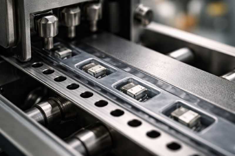
Beyond dimensional tolerance stacking, pocket geometry itself becomes a critical stability factor in high-speed SMT environments. A pocket design that performs adequately at moderate placement speeds can become mechanically unstable once dynamic indexing forces increase.
One of the primary geometric risk factors is excessive lateral clearance between the component body and pocket walls. At 30,000 CPH, minor side clearance may not generate noticeable movement. At 60,000 CPH or higher, acceleration forces during indexing can induce micro-sliding within the cavity. Even sub-millimeter displacement is sufficient to shift the pickup center outside optimal nozzle alignment.
Pocket depth control is another critical variable. Insufficient depth reduces vertical constraint, allowing lightweight components to experience micro-lift during rapid deceleration. Conversely, excessive depth can reduce vacuum pickup stability by altering the effective Z-height reference. Under high-speed operation, vertical geometry tolerance becomes as important as lateral control.
The corner radius design of the pocket also influences dynamic stability. Overly large radii reduce component constraint at critical contact points, while sharp or poorly controlled radii can introduce stress concentrations during forming, leading to inconsistent cavity shapes across the reel. High-speed SMT magnifies these inconsistencies.
In deeper pocket designs — particularly for taller or heavier components — forming limits become more pronounced. Material thinning during embossing can reduce structural rigidity at the pocket walls. Under repeated indexing cycles, these walls may flex slightly, increasing internal clearance dynamically even if static measurements remain compliant.
The engineering reality is clear:
Pocket geometry that works at 30,000 CPH may fail at 60,000 CPH.
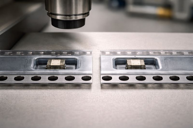
High-speed SMT effectively converts geometric tolerance into dynamic movement potential. Stability requires not only dimensional compliance but also optimized constraint geometry — balanced lateral clearance, controlled depth, and structurally stable pocket walls capable of maintaining shape under repetitive acceleration loads.
In high-throughput environments, pocket design must be evaluated not as a static cavity, but as a mechanical containment system operating under continuous dynamic excitation.
Root Cause 3: Material Rigidity Limits
Even when dimensional tolerances and pocket geometry are properly controlled, material behavior under dynamic stress can become the limiting factor in high-speed SMT stability.
Carrier tape is not a rigid mechanical component; it is a formed thermoplastic structure subjected to repetitive acceleration, deceleration, and vibration. As placement speeds increase, the tape experiences cyclical mechanical loading at a higher frequency. Under these conditions, material rigidity, elastic recovery characteristics, and structural damping properties directly influence performance.
Different materials exhibit fundamentally different behaviors:
-
PS (Polystyrene) typically offers good formability and cost efficiency. However, it has relatively lower impact resistance and limited structural resilience under repeated dynamic loading. At higher speeds, micro-flexing of pocket walls or slight sprocket hole deformation can accumulate over time.
-
PET (Polyethylene Terephthalate) provides improved tensile strength and better dimensional retention compared to PS. It demonstrates stronger resistance to tearing at sprocket holes but may still exhibit minor elastic deformation under rapid indexing stress.
-
PC (Polycarbonate) delivers superior rigidity, impact resistance, and structural stability. Under high-frequency mechanical cycling, PC maintains pocket geometry and hole integrity more consistently than PS or PET.
(See: PC Carrier Tape, PS Carrier Tape, PET Carrier Tape)
The key mechanism at high speed is micro-deformation and elastic rebound. During rapid feeder indexing, tension spikes occur at sprocket engagement points. The tape body absorbs this load and then rebounds. If the material exhibits excessive elasticity, small oscillations can propagate along the tape length. These oscillations may not be visible to the naked eye but can alter pocket positioning momentarily during pickup.
Additionally, high-speed vibration introduces resonance-like effects. Materials with lower stiffness may amplify vibrational energy rather than dampen it. This can slightly distort pocket geometry during critical pickup moments.
Importantly, static flatness inspection does not reveal these dynamic behaviors. A tape may measure dimensionally perfect on an inspection table but behave differently under continuous mechanical excitation.
As SMT speeds increase, material selection transitions from a cost-driven decision to a structural engineering decision. The material must not only hold its shape — it must maintain that shape under repeated high-frequency stress cycles without cumulative deformation.
At high throughput levels, rigidity becomes a functional requirement rather than a specification preference.
Root Cause 4: Cover Tape Peel Instability
In high-speed SMT environments, the cover tape removal process becomes a dynamic mechanical event rather than a simple protective film separation. As indexing speed increases, peel behavior directly influences component stability at the exact moment prior to pickup.
Cover tape performance is governed primarily by peel force consistency. Under controlled laboratory conditions, peel force is measured at a defined angle and speed. However, in real production environments, peel angle may fluctuate slightly, and peel speed increases proportionally with SMT throughput. This transforms peel behavior from a static parameter into a dynamic variable.
If peel force is too high, excessive upward tension may transmit force into the carrier tape structure. This can cause momentary pocket distortion or slight component lift at the moment of cover release. Lightweight components are especially sensitive to this disturbance. In extreme cases, partial component displacement can occur before nozzle engagement.
If peel force is too low, cover separation may become unstable. Inconsistent adhesion can create irregular peeling motion, leading to micro-vibrations or brief sticking–release cycles. These fluctuations can disturb component positioning or create unpredictable separation timing relative to pickup.
High-speed SMT magnifies the effect of peel-force variability. A peel force variation that is acceptable at moderate speed can become unstable when peel acceleration increases. Even small fluctuations across reel length may translate into statistical pickup inconsistencies.
Another factor is the release impulse. When cover tape detaches from a pocket cavity, a minor energy transfer occurs. At lower speeds, this impulse is negligible. At higher speeds, repeated rapid release events can introduce micro-movement in components with minimal pocket constraint.
(See: Cover Tape for Carrier Tape)
The engineering reality is that cover tape is not merely a protective layer; it is part of the dynamic system. Peel force must be controlled not only within specification limits but within a narrow stability band appropriate for high-speed indexing conditions.
In ultra-high-speed applications, peel stability becomes a synchronization requirement between feeder mechanics, tape material rigidity, and pocket geometry control.
Root Cause 5: Feeder Compatibility & Indexing Accuracy
Carrier tape performance in high-speed SMT cannot be evaluated independently from the feeder system. Even a dimensionally precise tape may exhibit instability if feeder indexing accuracy and engagement mechanics are not fully compatible with its tolerance profile.
Different feeder brands and models operate with varying indexing tolerances, drive mechanisms, and sprocket engagement geometries. Some systems apply more aggressive acceleration curves; others prioritize smoother motion profiles. These mechanical differences influence how dimensional variations in the tape are translated into positional deviation.
One of the most sensitive interaction points is the sprocket hole engagement interface. The D1 hole diameter and positional tolerance directly affect how precisely the feeder pins index the tape. Under dynamic conditions, even slight hole eccentricity or diameter drift can introduce micro-slippage during acceleration. At moderate speeds, this may remain functionally insignificant. At high speeds, it can alter pocket positioning relative to the expected pickup coordinate.
(See: Carrier Tape D1 Hole, Carrier Tape Pitch)
Pitch accuracy also plays a central role. While pitch tolerance may fall within EIA-481 limits, feeder indexing systems assume consistent cumulative spacing. In high-speed environments, repeated micro-variation in pitch can produce progressive alignment offset, especially across longer indexing sequences.
Another factor is feeder clamping and rail guidance design. If the tape width tolerance approaches the upper or lower boundary of specification, lateral play within the feeder track may increase. Under rapid indexing, this can translate into tape drifting or micro-oscillation.
It is important to recognize that feeder systems are not infinitely adaptive. They operate within defined mechanical compensation ranges. When carrier tape dimensional variation approaches these limits, high-speed acceleration reduces the system’s ability to self-correct between indexing cycles.
In practice, high-speed stability requires synchronization between:
-
Sprocket hole precision
-
Pitch control consistency
-
Tape width tolerance
-
Feeder indexing mechanics
Carrier tape and feeder must function as a calibrated pair. Without compatibility validation under real operating speeds, dimensional compliance alone does not guarantee stable performance.
Why Passing EIA-481 Does Not Guarantee High-Speed Stability
EIA-481 defines dimensional tolerances, pocket geometry limits, pitch spacing, sprocket hole dimensions, and peel force ranges for embossed carrier tape systems. It establishes a critical baseline for interoperability and industry standardization. However, the specification framework is fundamentally static.
Measurements defined under EIA-481 are performed under controlled inspection conditions. Tape width, pitch, pocket alignment, D1 hole diameter, and cover tape peel force are verified at rest or at standardized peel speeds. The goal is dimensional compliance — not dynamic performance validation.
High-speed SMT, by contrast, is a dynamic mechanical environment. Acceleration curves, vibration frequency, feeder drive impulses, and peel rate variability introduce forces that are not simulated during static inspection.
This distinction is central:
Specification compliance confirms dimensional acceptability.
High-speed stability requires dynamic resilience.
A carrier tape may pass every listed parameter in the standard yet still exhibit instability when subjected to:
-
Rapid indexing acceleration
-
Repetitive mechanical loading cycles
-
High-frequency peel events
-
Continuous feeder pin engagement stress
EIA-481 tolerances are designed to ensure interchangeability across global manufacturing systems. They define allowable deviation bands. However, operating near the upper or lower edge of those bands increases dynamic sensitivity at higher SMT speeds.
For example:
-
A pitch tolerance at the high side of specification
-
A sprocket hole positional deviation near its limit
-
A peel force at the upper acceptable threshold
Individually, each remains compliant. Collectively, under high-speed conditions, they can interact to produce cumulative misalignment.
In other words:
Specification compliance ≠ engineering optimization.
EIA-481 answers the question:
“Is this tape within standardized dimensional limits?”
High-speed SMT demands a different question:
“Is this tape dynamically stable under accelerated mechanical stress?”
For further dimensional reference, see Carrier Tape Specifications.
Engineering validation for high-speed production must therefore extend beyond checklist compliance. It requires evaluation under realistic indexing speeds, feeder compatibility testing, and dynamic performance verification. Static tolerance alone cannot predict high-throughput reliability.
Engineering Prevention Strategies
Preventing carrier tape instability in high-speed SMT environments requires engineering foresight rather than reactive troubleshooting. The objective is not to fix isolated symptoms after yield loss occurs, but to anticipate dynamic stress conditions during the design validation stage.
High-speed SMT should be treated as a design threshold condition. Once placement rates exceed moderate production speeds, dimensional tolerance, geometry control, and material rigidity must be evaluated against elevated dynamic loading.
A practical engineering logic model can be applied:
If SMT speed exceeds a defined high-speed threshold → dimensional tolerance must tighten.
As indexing acceleration increases, cumulative pitch variation and sprocket hole positional deviation become more sensitive. Operating near specification limits is no longer sufficient. Tightened internal tolerances reduce the amplification effect under dynamic indexing.
If the component mass is low or center of gravity is high → pocket geometry becomes critical.
Lightweight components are more vulnerable to peel impulse and acceleration-induced movement. Taller components are more sensitive to rotational instability. In such cases, lateral clearance must be minimized within safe insertion limits, and pocket depth must be precisely controlled to prevent micro-lift.
If yield requirement is stringent or defect tolerance is minimal → material selection must upgrade.
For applications requiring near-zero placement error rates, material rigidity becomes a risk mitigation tool. Higher-stiffness materials reduce dynamic deformation and improve indexing consistency under high-frequency mechanical cycles.
Additionally:
-
When feeder systems operate with aggressive acceleration curves, sprocket hole precision must exceed baseline specification consistency.
-
When cumulative reel length is long, pitch stability across the full tape length must be statistically validated, not sampled selectively.
Prevention is therefore conditional and system-dependent. It requires alignment between SMT speed, component characteristics, feeder mechanics, and carrier tape design parameters.
High-speed SMT should be approached as a dynamic validation problem, not merely a dimensional inspection task. Engineering stability is achieved when design decisions anticipate stress amplification before production begins.
When Custom Carrier Tape Becomes Necessary
In many production environments, standard carrier tape designs perform adequately within conventional SMT speed ranges. However, as operational requirements shift toward ultra-high throughput, non-standard component geometries, or near-zero defect tolerance, standard configurations may no longer provide sufficient stability margins.
Custom carrier tape becomes necessary when component characteristics exceed the containment capability of standardized pocket designs. Irregular body shapes, asymmetrical mass distribution, ultra-thin lead frames, or fragile terminations can require modified pocket geometry to prevent dynamic movement under acceleration.
High-speed SMT environments operating significantly above typical throughput thresholds may also require tighter internal tolerances than those defined by baseline industry specifications. In such cases, controlled pocket-to-hole alignment, reinforced pocket wall thickness, or optimized corner radius geometry may need to be engineered specifically for the application.
Another scenario arises when yield sensitivity is extremely high — such as in automotive, medical, or high-reliability electronics manufacturing. When placement deviation tolerance is minimal, dimensional compliance alone is insufficient. Customization allows engineering control over:
-
Reduced lateral clearance bands
-
Optimized depth-to-component ratio
-
Enhanced material rigidity selection
-
Controlled peel-force pairing
(See: Carrier Tape Design Guide)
Custom carrier tape is not always required. But when dynamic stress conditions exceed standard stability margins, or when component design introduces unique mechanical sensitivity, customization transitions from optional to necessary.
In high-speed SMT, custom engineering is often the most reliable method to eliminate compounded risk factors before they manifest in production yield loss.
Summary: High-Speed SMT as a Design Stress Test
High-speed SMT is not the origin of carrier tape failure. It is the amplifier.
When placement rates increase, acceleration forces rise, peel events accelerate, and indexing cycles intensify. These dynamic conditions do not introduce new failure mechanisms — they expose the hidden limits of dimensional control, material rigidity, pocket geometry, and feeder synchronization.
A carrier tape that performs adequately at moderate speed may already contain marginal design weaknesses. High-speed operation simply reduces the tolerance margin available to absorb those weaknesses.
Tolerance stack-up becomes dynamic misalignment.
Excess lateral clearance becomes component rotation.
Material elasticity becomes indexing instability.
Peel-force fluctuation becomes pickup disturbance.
From an engineering perspective, high-speed SMT functions as a stress test applied to the entire tape–feeder–component system. It reveals whether the design was optimized only for specification compliance — or for real dynamic performance.
Designing for high-speed stability therefore requires anticipating amplified mechanical effects during the development stage. Static inspection confirms compliance. Dynamic validation confirms reliability.
In advanced SMT environments, success is not defined by passing specification — it is defined by maintaining positional stability under continuous acceleration.



 Emial
Emial John Mr


