








Component Rotation in Carrier Tape: Causes, Risks, and Design Solutions for SMT Assembly
What Is Component Rotation in Carrier Tape?
Component rotation in carrier tape refers to the angular displacement of a part inside its embossed pocket before the pick-and-place process. Instead of remaining fixed in its intended orientation, the component shifts or turns within the cavity, creating a measurable deviation from its nominal alignment. This rotation may be subtle—only a few degrees—or significant enough to affect placement accuracy during high-speed SMT assembly.
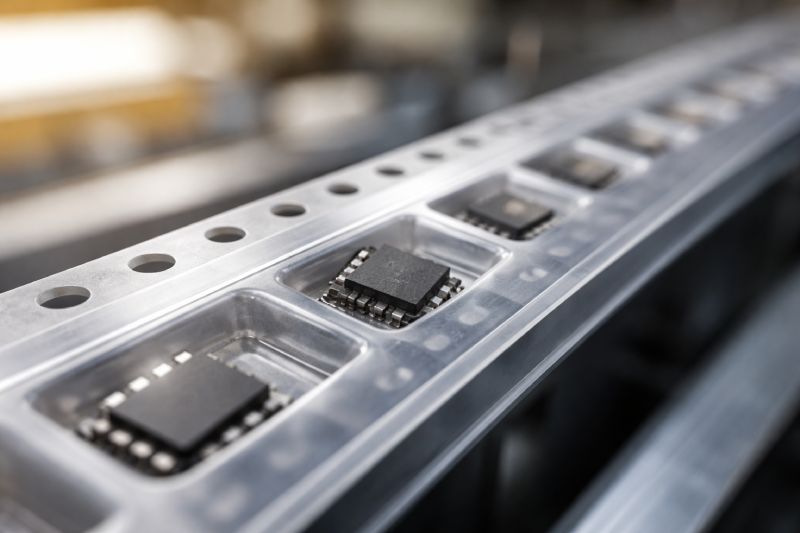
Rotation can occur at multiple stages of the supply chain. During transportation and storage, vibration and mechanical shock may cause movement if lateral or vertical stability is insufficient. During feeder indexing, dynamic acceleration and deceleration forces can further amplify any existing clearance inside the pocket. In high-speed SMT environments, even small angular variations can be magnified by rapid tape advancement and vacuum pick-up dynamics.
The direct consequence is a mismatch between the expected pick orientation and the actual component position. When the nozzle engages a rotated part, the placement head may transfer that misalignment directly onto the PCB pad layout.
Component rotation occurs when a part shifts or turns inside the carrier tape pocket, leading to misalignment during pick-and-place.
Why Component Rotation Matters in High-Speed SMT
In high-speed SMT production, even minor angular instability inside the carrier tape can translate into measurable placement errors. Modern pick-and-place systems operate at extremely high indexing speeds, where positional precision depends on consistent component orientation at the moment of vacuum pickup. When a component rotates inside the pocket—even by a small angle—the system may not fully compensate before placement.
The first impact appears at the pick position. A rotated part shifts its center of gravity relative to the expected pickup point, potentially causing nozzle misalignment or unstable vacuum engagement. This can lead to slight tilting, off-center pickup, or micro-slip during transfer.
That deviation then propagates to the placement stage. A small angular offset
→ creates a pick orientation error
→ results in pad-to-lead mismatch on the PCB
→ increases the probability of solder bridging, insufficient wetting, or tombstoning (for passive components).
While a few degrees of rotation may seem negligible, high-density PCB layouts leave minimal tolerance for misalignment. In advanced assemblies with fine-pitch ICs or small passives, rotational instability directly affects yield.
Ultimately, component rotation is not just a cosmetic alignment issue—it is a process stability risk that can reduce placement accuracy, increase rework rates, and compromise overall production efficiency.
Root Causes of Component Rotation in Carrier Tape
Component rotation rarely results from a single dimensional deviation. In most cases, it is the outcome of mechanical clearance, structural flexibility, tolerance variation, and dynamic forces acting together. Understanding these root causes requires analyzing the pocket–component relationship as a controlled mechanical system rather than a simple packaging cavity.
Below are the primary engineering factors that contribute to rotation risk.
Excessive Pocket Clearance
Lateral clearance is the most direct contributor to rotation.
If the pocket width significantly exceeds the component body width, the part gains freedom of movement inside the cavity. Even when the nominal design appears acceptable, small increases in side gap can allow angular displacement during vibration or feeder indexing.
When clearance is too large:
-
The component can slide laterally within the pocket.
-
Rotational freedom increases due to uneven force distribution.
-
Dynamic acceleration inside the feeder amplifies movement.
The issue becomes more pronounced in high-speed environments, where rapid tape advancement generates inertial forces. A component with excessive lateral gap does not remain constrained against the pocket wall, allowing small shifts that accumulate into measurable angular rotation.
Proper clearance design is not about maximizing space—it is about controlling movement while still allowing smooth pick access.
Insufficient Pocket Depth
Vertical stability is equally important.
If pocket depth is too shallow relative to component height, the part may not sit securely within the cavity. During transport or reel handling, minor shock or vibration can cause micro-lifting or bouncing. Once the component momentarily loses full bottom contact, it becomes more susceptible to rotation upon settling.
Shallow pockets can lead to:
-
Reduced vertical containment
-
Increased sensitivity to vibration
-
Instability during feeder acceleration
Conversely, excessively deep pockets may create other problems, such as unstable vacuum pickup due to excessive vertical clearance. The key is achieving balanced depth that stabilizes the part without restricting pick performance.
Inconsistent Carrier Tape Tolerance
Even when nominal dimensions are correct, manufacturing tolerance variation can introduce instability.
Critical variables include:
-
Pocket width tolerance
-
Pocket length tolerance
-
Pocket center alignment
-
Pitch accuracy
If these tolerances fluctuate across production batches, the effective clearance between pocket and component may vary. This phenomenon—known as tolerance stack-up—can result in certain pockets having more free space than intended.
For example:
Nominal lateral clearance
-
pocket dimension tolerance
-
component body tolerance
= unpredictable dynamic gap
In high-speed SMT lines, these accumulated variations can translate into inconsistent rotation behavior from reel to reel.
Material Rigidity & Structural Stability
Carrier tape material plays a structural role in maintaining pocket geometry.
Common materials such as PS, PET, and PC differ significantly in rigidity and deformation resistance. Softer materials may flex slightly under mechanical stress or during winding on reels. This deformation can alter effective pocket shape or sidewall stability.
Material rigidity influences:
-
Pocket wall stiffness
-
Resistance to deformation during transport
-
Dimensional retention under feeder pressure
In applications requiring tight rotational control—especially for small IC packages or lightweight components—material selection directly affects stability.
Cover Tape Peel Force Imbalance
The interaction between carrier tape and cover tape also affects rotation behavior.
If peel force is too high, the cover tape may momentarily lift the component during peeling, inducing angular displacement just before pickup. If peel force is too low, the component may shift during shipping due to insufficient top restraint.
Peel force imbalance can cause:
-
Pre-pick rotation during tape opening
-
Micro-movement during transport
-
Inconsistent pickup orientation
Controlled peel force calibration is therefore essential to maintaining consistent component positioning.
In practice, component rotation is rarely caused by a single parameter. It is typically the result of pocket clearance, depth control, tolerance variation, material rigidity, and peel force behavior interacting under dynamic SMT conditions.
How Tolerance Stack-Up Contributes to Rotation
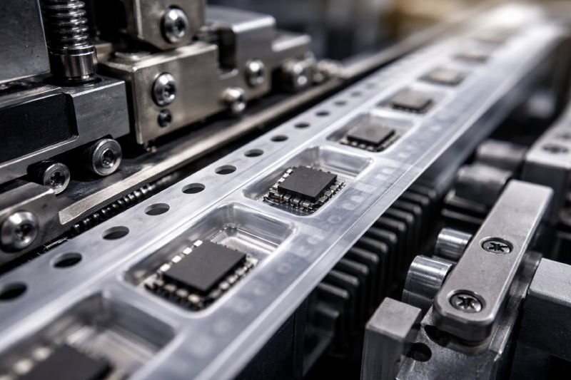
Tolerance stack-up is one of the most underestimated contributors to component rotation in carrier tape systems. Even when both the component and the pocket are designed within acceptable nominal dimensions, accumulated tolerances can create unintended dynamic clearance.
To understand this, consider three variables:
-
Pocket width tolerance
-
Component body width tolerance
-
Pocket center alignment tolerance
Each dimension may individually fall within specification. However, when combined, they determine the actual effective lateral gap inside the pocket.
From an engineering perspective:
Nominal pocket width
– nominal component width
= nominal clearance
But in reality:
(Pocket width + positive tolerance)
– (Component width – negative tolerance)
= maximum possible free movement
This accumulated variation defines the worst-case dynamic gap. If that gap exceeds the stability threshold for the given component weight and SMT speed, rotation becomes likely.
The effect becomes more pronounced in high-speed feeder systems. Rapid indexing introduces acceleration forces that act laterally on the component. When clearance is minimal, the pocket wall constrains motion. When tolerance stack-up increases free space, the component can pivot within the cavity under inertial load.
Additionally, pitch tolerance variation can introduce secondary instability. If pocket positioning relative to sprocket holes fluctuates, feeder indexing may not align perfectly with pocket geometry. This slight mechanical misregistration can further amplify rotational behavior during pickup.
Tolerance stack-up therefore transforms what appears to be a static dimensional issue into a dynamic stability problem. The interaction between dimensional variation and feeder acceleration determines whether nominally compliant designs perform consistently in production.
In high-speed SMT environments, controlling rotation is not just about designing nominal clearance—it is about engineering for worst-case tolerance accumulation under dynamic conditions.
Component Types More Prone to Rotation
Not all components respond to pocket clearance and dynamic forces in the same way. Certain package types are inherently more susceptible to rotation due to their weight, geometry, and center-of-gravity characteristics. Understanding which components carry higher rotational risk allows engineers to apply tighter design controls where necessary.
Lightweight components are particularly vulnerable. When mass is low, inertial resistance decreases. During feeder acceleration or vibration, a lightweight part requires less force to shift position. Even small lateral gaps can permit measurable angular displacement because there is insufficient mass to stabilize the component against the pocket wall.
Thin IC packages—such as QFN or thin SOP variants—can also exhibit rotational sensitivity. Their low profile reduces vertical confinement inside the pocket. If pocket depth is not optimized, the component may experience minor lifting or tilting during transport, increasing the likelihood of rotation before pickup.
Small passive components (e.g., chip resistors and capacitors) present a different challenge. Their compact size means that absolute clearance values may appear small, but relative clearance (clearance-to-body ratio) can still be high. Additionally, their symmetrical shape can make slight angular shifts difficult to visually detect while still affecting pad alignment during placement.
Asymmetric geometry parts—such as connectors, diodes, or components with uneven mass distribution—are especially prone to rotational instability. An off-center center of gravity creates uneven contact pressure inside the pocket. Under dynamic conditions, these components tend to pivot more easily around their mass bias.
In summary, rotation risk increases when component mass is low, profile is thin, geometry is asymmetric, or clearance is proportionally large relative to body dimensions. Recognizing these risk profiles early in design planning helps prevent downstream placement instability in high-speed SMT production.
How to Evaluate Rotation Risk in Your Project
Evaluating rotation risk in a project requires a systematic approach that balances the physical attributes of the components, the design of the carrier tape, and the operational parameters of the SMT production line. The goal is to assess the likelihood of component rotation at various stages of the process and take proactive measures to minimize its impact.
Engineering Decision Framework
-
If pocket clearance exceeds the necessary threshold, the risk of rotation increases
The first rule of thumb is to assess the clearance between the component and the pocket. If the lateral clearance is too wide, the part may shift or rotate inside the pocket. This can happen during transport or while the tape is advancing through the feeder. Therefore, the key decision point is determining the minimum clearance required for stable component retention. If clearance exceeds this threshold, the risk of rotation rises significantly. -
If SMT speed is high, dynamic instability increases
High-speed SMT lines generate acceleration forces during feeder indexing that can amplify the effect of small lateral gaps. In such environments, even minimal clearance can result in rotational instability. Therefore, higher speed machines require greater control over component positioning, with tighter tolerance specifications and more rigid material selections to reduce movement within the tape pockets. -
If component weight is low, rotation is more likely
Lightweight components—especially those with thin profiles or asymmetrical geometries—are less resistant to dynamic forces. As a result, they are more susceptible to shifting inside the pocket during transport or feeder movement. For these types of components, the rotation risk is higher, and engineers must account for additional stability measures, such as material choice, pocket depth, and clearance optimization.
Practical Evaluation Steps
-
Assess Component Size and Geometry: Consider the component’s physical dimensions, weight, and center-of-gravity distribution. Thin or lightweight components with large relative clearance are more prone to rotation.
-
Examine Pocket Design: Verify the clearance between the component and the pocket. Ensure it is minimal but sufficient for smooth indexing without compromising stability. Monitor whether lateral clearance or vertical depth needs tightening.
-
Consider Production Speed: Account for the feeder‘s speed and the dynamic forces acting on the tape. If you are working with high-speed SMT systems, use tighter tolerances to avoid rotational instability under acceleration.
-
Check Tolerance Stack-Up: Evaluate whether manufacturing tolerances for the carrier tape and components are contributing to accumulated variations that increase clearance beyond acceptable limits.
By incorporating these factors into an engineering decision framework, rotation risks can be effectively assessed and mitigated during the design phase, ensuring more stable component placement during SMT assembly.
Design Factors That Minimize Component Rotation
Minimizing component rotation in carrier tape requires a holistic approach to design, encompassing everything from pocket geometry to material selection and feeder compatibility. Each design choice must be made with consideration for the dynamic conditions that the components will encounter during transport, storage, and high-speed SMT assembly. Below are the key design factors that can be optimized to reduce the likelihood of component rotation.
Pocket Geometry Optimization
The first and most critical design factor is optimizing the pocket geometry. Ensuring that the pocket is well-suited to the specific component is essential for minimizing lateral movement and rotational instability. Key considerations include:
-
Precise Pocket Dimensions: Ensure that the pocket width, depth, and length are tightly controlled to minimize excess clearance. For lightweight components or small IC packages, reducing lateral clearance prevents shifting within the pocket. Similarly, controlling depth ensures that the component sits securely without bouncing or tilting.
-
Rounded Corners and Smooth Walls: Sharp corners and abrupt edges can create uneven pressure points, which could cause components to rotate or shift. Designing the pocket with smooth, rounded corners allows for more even distribution of forces, keeping the component stable within the cavity.
-
Lateral and Vertical Containment: The pocket should provide both lateral and vertical containment. The lateral containment prevents sideways shifting, while the vertical containment ensures that the component does not lift or bounce during transport. In this way, the part remains locked in place throughout the process.
Controlled Lateral Clearance
Controlled lateral clearance is one of the most important design aspects for preventing component rotation. The clearance between the component and the pocket should be minimal but sufficient for smooth feeding into the pick-and-place machine. Too much space allows the component to move freely, while too little clearance could hinder the machine’s ability to pick the component accurately. Finding the right balance is crucial.
In high-speed SMT systems, where tape advances quickly, excessive clearance can result in unintended shifting. Therefore, it is recommended to design the clearance such that the component has just enough space to be picked reliably but not so much that it can rotate.
Material Selection (PC vs PS)
The material selection for both the carrier tape and the component is another vital factor in minimizing rotation. Materials with higher rigidity are better at retaining pocket geometry and preventing deformation during transport, indexing, and pick-up. The most commonly used materials for carrier tapes are Polycarbonate (PC) and Polystyrene (PS), both of which have distinct characteristics:
-
Polycarbonate (PC): PC is stiffer and less prone to deformation, making it ideal for maintaining precise pocket geometry and preventing rotation during dynamic movements. It also performs well under high-speed conditions, maintaining its structural integrity better than softer materials.
-
Polystyrene (PS): PS is more flexible and tends to deform under pressure or when subjected to vibration. While it may be cost-effective for some applications, it may be less suitable for high-speed, high-precision environments where rotational stability is critical.
When designing carrier tape for components prone to rotation, selecting a stiffer material like PC will provide better stability and minimize the risk of pocket deformation, which can lead to rotation.
Peel Force Calibration
Another essential factor is peel force calibration. If the cover tape peel force is too high, it can momentarily lift the component during the tape-opening process, leading to rotational shifts before pick-and-place. On the other hand, if the peel force is too low, the component may become loose during storage or transport, increasing the risk of rotation when the tape is fed through the machine.
To mitigate this, calibrating the peel force is crucial. The peel force should be set just high enough to ensure proper removal of the cover tape without causing the component to shift or rotate. This balance is especially important in environments with lightweight or small components, where small shifts can lead to significant alignment issues.
Feeder Compatibility Consideration
Lastly, it’s essential to consider the feeder compatibility during the design phase. The feeder is responsible for advancing the carrier tape and positioning the component for pickup. The feeder’s speed, precision, and the way it grips the tape can significantly impact the risk of rotation.
-
Feeder Speed: Faster feeder speeds result in higher dynamic forces acting on the component. Therefore, ensuring that the feeder system is compatible with the carrier tape design, especially in high-speed environments, is essential for maintaining stability and preventing rotation.
-
Precision and Alignment: The feeder must be designed to precisely align the carrier tape with the pick-and-place machine’s nozzle. Any misalignment, even by a few microns, can create rotational instability by causing the component to shift slightly inside the pocket before pickup.
Designing the carrier tape system with feeder compatibility in mind ensures that the tape will feed smoothly and that components remain aligned in the pocket throughout the process, reducing the chances of rotation.
Conclusion
Reducing component rotation in carrier tape is not a one-size-fits-all approach—it requires a tailored design process that considers pocket geometry, material properties, clearance, and feeder integration. By optimizing these design factors, engineers can significantly reduce the risk of rotational instability, leading to more reliable and precise component placement in high-speed SMT environments.
Real-World Manufacturing Perspective
In real-world manufacturing, component rotation often presents itself as a complex issue rather than a simple, one-dimensional problem. Unlike laboratory conditions where tape and component dimensions are strictly controlled, high-volume production environments introduce a range of dynamic variables that can affect the stability of components inside carrier tape pockets. These variables include feeder performance, environmental conditions, and material degradation over time, all of which contribute to the unpredictability of component rotation.
Rotation Is Not Just a Single-Dimension Problem
From a manufacturing perspective, rotation is rarely caused by just one isolated issue. While pocket clearance, depth, and material selection are crucial, these factors must be considered in the broader context of the entire SMT process. Rotation may occur not only due to pocket design but also as a result of how the tape is handled, the speed of the feeder, the vibrations during transportation, and the interaction between the component and the tape throughout the production line.
For example, a perfectly designed pocket with minimal clearance may still result in rotation if the feeder speed is too high, or if the material of the carrier tape deforms under the stress of high-speed indexing. In such cases, even a small gap can cause the component to shift during tape advancement, leading to rotational misalignment when the part is picked.
Additionally, component type plays a significant role in the rotation issue. Lightweight or asymmetrical components are more likely to rotate, regardless of the tight tolerances in the pocket design. These components are prone to instability due to their lower mass and uneven center of gravity, which can make them more susceptible to rotation under even minor forces.
Prototyping and Testing: Verifying Rotation Behavior
During the prototype stage, verifying the effectiveness of the carrier tape design and its resistance to rotation is crucial. Engineers must simulate real-world conditions, testing the carrier tape under dynamic forces similar to those in the production environment. It’s not sufficient to rely solely on theoretical designs and static measurements. Real-world testing includes subjecting the carrier tape to vibrations, feeder cycles, and even environmental factors like temperature changes that may affect the material properties of the tape.
The initial validation phase might involve:
-
Vibration Testing: Exposing the tape to real-world shipping and handling conditions to simulate how vibrations and bumps might affect component placement.
-
Feeder Testing: Running the tape through the feeder at varying speeds to assess the impact of dynamic forces on component stability and alignment.
-
Environmental Stress Testing: Assessing how extreme temperatures or humidity levels affect material rigidity, pocket geometry, and, ultimately, the risk of rotation.
While laboratory testing can simulate certain conditions, real-world trials are essential for identifying issues that might not be apparent in controlled environments. This testing helps identify whether rotation occurs at particular stages—whether during transport, feeder feeding, or pickup.
The Difference Between Prototype and Mass Production
In high-volume mass production, what works well in small batches or prototype runs may not translate to larger-scale operations. Small variations in feeder settings, pocket tolerances, or material performance that might have been negligible in a laboratory environment can become more significant when scaled up. This difference is often attributed to the dynamic loading in mass production, where components are indexed at a much faster rate.
Mass production challenges include:
-
Feeder variability: Even slight inconsistencies in feeder calibration or alignment can result in rotational instability during high-speed indexing.
-
Material degradation: Over time, carrier tape materials can experience wear, which may lead to dimensional drift or loss of rigidity.
-
Environmental factors: Changes in environmental conditions (e.g., temperature or humidity) in a factory or shipping process can affect the behavior of the carrier tape, leading to component rotation that was not evident in earlier testing.
To ensure consistent performance, manufacturers must continually evaluate their systems, from feeder setup to material sourcing, to prevent rotation from impacting yield and efficiency in mass production.
Conclusion: A Systems-Level Approach
From a real-world manufacturing perspective, preventing component rotation is not just about optimizing one element in the supply chain—such as pocket design or feeder speed. It requires a systems-level approach that considers how each part of the SMT process interacts and influences the overall stability of the component. Through prototyping, dynamic testing, and careful consideration of all factors involved, manufacturers can ensure that rotation risks are minimized, leading to higher precision and reliability in high-speed SMT assembly lines.
When Rotation Indicates a Deeper Design Issue
While component rotation is often associated with isolated factors like pocket clearance or feeder speed, it can also serve as a symptom of a deeper design issue within the overall system. If rotation becomes a recurring problem despite optimization efforts, it may indicate underlying design flaws that require more comprehensive changes. Identifying these systemic issues is crucial for ensuring long-term reliability and efficiency in the production process.
Tolerance Mismatch
One of the most common root causes of persistent rotation issues is tolerance mismatch. This occurs when the tolerances between the carrier tape, components, and the feeder system are not well-aligned or coordinated. For example, if the pocket tolerance is too loose or too tight relative to the component‘s dimensions, rotational instability becomes more likely, even under normal operating conditions.
The tolerance mismatch can be particularly challenging because it often involves multiple parts of the system. A component that is slightly oversized for the pocket might still be picked and placed correctly, but over time, the combination of tolerances in the pocket, component, and feeder will lead to gradual misalignment and rotation.
This issue can be exacerbated by cumulative tolerance stack-up, where small variations in each element of the system add up to create a large deviation in the final alignment. This is especially problematic in high-speed production lines, where even small variations can lead to significant problems with component placement and yield.
Incorrect Material Selection
Material selection is another potential indicator of deeper design issues. If component rotation persists despite addressing pocket geometry and clearance, the materials used for the carrier tape and the components themselves may be at fault. For example, materials that are too soft, like Polystyrene (PS), can cause deformation over time, leading to a loss of pocket geometry and stability. On the other hand, materials that are too rigid, like Polycarbonate (PC), can increase the likelihood of pocket cracking under stress, affecting the overall system’s performance.
Incompatibility between materials in the carrier tape, cover tape, and components can lead to performance degradation that manifests as rotation. Over time, the wear and tear from feeder systems or handling equipment may introduce additional stresses, further exacerbating the rotational issues.
Selecting the right material requires a balanced approach, factoring in rigidity, flexibility, and the expected operating conditions of the tape throughout its lifecycle.
Feeder and Pocket System Mismatch
Rotation can also indicate an issue with the compatibility between the feeder system and the carrier tape design. If the feeder speed is too high for the pocket design, the dynamic forces during indexing may be more than the component can withstand. As a result, even with tight tolerances and correct material selection, rotation may still occur. This is particularly true in high-speed SMT lines, where the forces during feeder indexing can cause components to shift even in well-designed pockets.
A mismatch between the pocket design and feeder type can also manifest in misalignment between the feeder sprocket holes and the pockets. If the carrier tape isn’t aligned correctly with the feeder’s pick-and-place mechanism, slight variations in the position of the pockets can lead to inconsistent component placement, causing rotation during the pickup process.
System-Level Design Thinking
When component rotation becomes a systemic issue, it is essential to shift to a system-level design approach. Rather than addressing the problem in isolation—by changing just the pocket or the material—designers must consider how every part of the process interacts. This includes:
-
Pocket and component compatibility: Ensuring that the pocket dimensions, material, and tolerance stack-up are fully aligned with the component’s size, weight, and geometry.
-
Feeder system integration: Evaluating the feeder’s speed, alignment, and mechanical setup to ensure it works harmoniously with the carrier tape and component design.
-
Material properties: Carefully selecting materials that will maintain dimensional stability and resistance to wear over time, taking into account the stresses placed on the carrier tape during production and transport.
In short, component rotation is often a signal that there is a systemic issue with the overall design and interaction of key system components. To resolve this effectively, engineers must adopt a holistic approach, addressing the underlying root causes and ensuring that the entire system is optimized for stability, reliability, and precision.
Conclusion: Addressing Root Causes for Long-Term Stability
When component rotation indicates a deeper design issue, the solution lies in a comprehensive reevaluation of the entire carrier tape and SMT system. Tolerance mismatch, incorrect material selection, and feeder-pocket incompatibility are common systemic causes that can lead to persistent rotational instability. By adopting a system-level approach and addressing these issues at their root, manufacturers can ensure long-term stability, reduced rework rates, and improved overall yield in high-speed SMT assembly lines.
Summary: Component Rotation as a System-Level Stability Problem
Component rotation in carrier tape is not merely a localized issue confined to pocket geometry or feeder misalignment. It is a system-level problem that arises from the interaction of multiple factors, including pocket clearance, material rigidity, feeder dynamics, component geometry, and manufacturing tolerances. When rotation occurs, it is often the result of an imbalance in one or more of these elements that, when combined, compromise the stability and precision of the SMT assembly process.
Key Takeaways:
-
Component rotation is a complex, multi-dimensional issue that arises due to the interplay of clearance, material properties, pocket design, feeder dynamics, and tolerance variations.
-
The root causes of rotation can range from excessive pocket clearance and insufficient pocket depth to tolerance stack-up and inconsistent material properties, all of which contribute to the likelihood of misalignment during pick-and-place.
-
High-speed SMT environments exacerbate rotational issues due to increased dynamic forces. As the feeder speed increases, even minor clearance discrepancies or slight shifts in component position can lead to misalignment and yield reduction.
-
System-level design thinking is crucial to addressing rotation. Rather than focusing on isolated fixes, engineers must optimize the entire process, from pocket and component design to feeder compatibility and material selection.
-
Proactive evaluation of rotation risks during the design phase—including careful consideration of component type, clearance, and material rigidity—can help identify potential issues before they manifest in production.
In conclusion, component rotation must be approached as a systemic issue, requiring comprehensive solutions that span all aspects of the carrier tape design, SMT process, and feeder configuration. By understanding the interdependence of these factors and addressing them holistically, engineers can ensure greater consistency, accuracy, and yield in high-speed SMT production, ultimately improving overall process efficiency.



 Emial
Emial John Mr


