








Carrier Tape Peel Force Explained for Stable SMT Assembly
What Is Carrier Tape Peel Force?
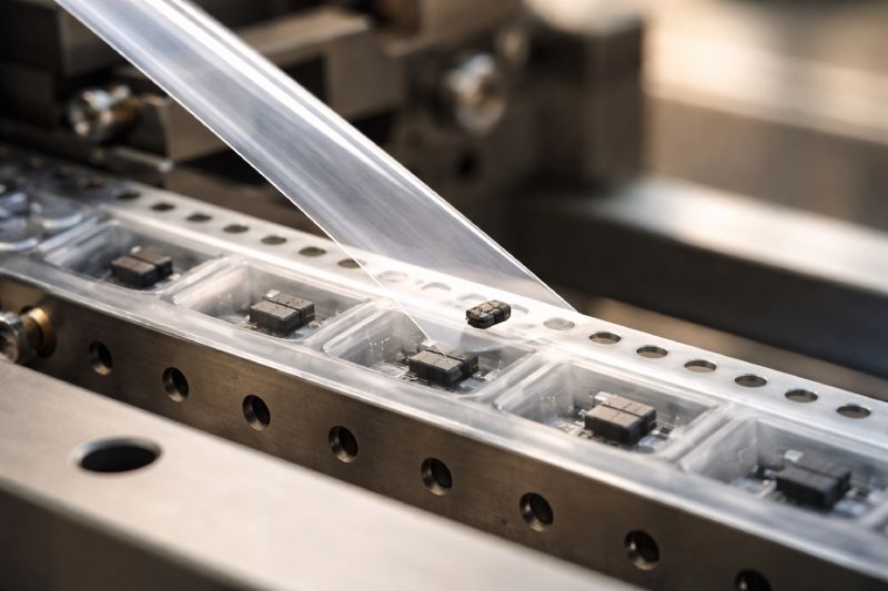
Carrier tape peel force refers to the controlled force required to separate the cover tape from the carrier tape during SMT feeding. It is measured while the cover tape is peeled back at a defined angle and speed, simulating real production conditions.
Unlike material strength or thickness, peel force is not a static property. It is a dynamic process parameter influenced by sealing conditions, material compatibility, and environmental factors. The interaction between the carrier tape pocket geometry and the selected Cover Tape for Carrier Tape plays a critical role in determining how consistently components are retained and released.
In practical terms, peel force directly affects how components behave at the exact moment of exposure to the pick-and-place nozzle within the Tape and Reel Packaging system.
Carrier tape peel force is the controlled force required to separate cover tape from carrier tape during SMT feeding, directly affecting component retention and release stability.
Why Peel Force Is Critical in SMT Assembly
Peel force directly influences release stability during SMT feeding. When the cover tape separates from the carrier tape, the component transitions from a retained state inside the pocket to an exposed state ready for pick-up. This transition must be controlled and repeatable.
The causal chain is clear:
Peel force → release stability → component movement → pick accuracy → placement yield
If peel force fluctuates, the release timing shifts. Even minor instability at the moment of separation can cause micro-movement inside the pocket. That movement affects nozzle alignment, vacuum engagement, and ultimately placement accuracy on the PCB.
It is important to understand that higher peel force does not automatically mean better security. Excessive force can introduce mechanical stress and destabilize the release moment. On the other hand, lower peel force does not necessarily improve smoothness. Too little resistance may compromise component retention before or during feeding.
In high-speed SMT environments, stability—not magnitude—is the priority. Consistent peel behavior ensures predictable release timing, controlled component exposure, and reliable placement yield across long production runs.
What Happens If Peel Force Is Too High?
When peel force is excessively high, instability does not appear immediately as a simple “hard-to-peel” issue. Instead, it creates a chain of mechanical side effects inside the feeder system.
First, higher peel force increases lifting tension on the cover tape. As the tape is pulled back, the upward force transfers partially to the carrier tape body. This can lead to slight carrier tape deformation, especially in thinner PS materials or long feeding runs. Even minimal deformation can alter pocket geometry during the release moment.
Second, the energy stored in the stretched cover tape may release suddenly when separation occurs. This abrupt release can cause components to jump or shift inside the pocket at the exact moment they become exposed. For lightweight components, this micro-movement is enough to reduce pick consistency.
Additionally, excessive peel resistance increases mechanical load on feeder components. Over time, higher tension can contribute to feeder strain, inconsistent indexing, or premature wear of guiding rails and peel mechanisms.
In short, high peel force creates tension accumulation → sudden release energy → component disturbance. The visible symptom may be pick inconsistency, but the root mechanism is dynamic instability during separation.
What Happens If Peel Force Is Too Low?
When peel force is too low, the system may appear smooth at first glance. However, insufficient resistance during separation often creates greater instability—especially in high-speed SMT environments.
One of the first risks is component escape during transport. If the sealing strength between cover tape and carrier tape is weak, vibration during reel handling or feeder indexing can gradually reduce pocket retention. Lightweight components are particularly vulnerable to shifting or rotating before they even reach the pick position.
Low peel force also affects release timing consistency. If the cover tape separates too easily, the release moment may occur slightly earlier than expected. This alters the synchronization between feeder indexing and nozzle positioning. In precision placement processes, even small timing deviations can reduce pick accuracy.
Another critical factor is vibration sensitivity. At high feeder speeds, dynamic forces increase significantly. With insufficient peel resistance, the cover tape may flutter or lift unpredictably, amplifying internal pocket movement.
In high-speed SMT lines, low peel force can be more dangerous than high peel force. While excessive force introduces mechanical tension, insufficient force compromises component retention and release control—both of which directly affect placement stability and yield.
Factors That Influence Peel Force
Peel force is not determined by a single variable. It results from the interaction between materials, sealing parameters, and environmental conditions. Stable peel performance depends on how well these factors are matched within the complete tape system.
Cover Tape Type (Heat-Activated vs Pressure-Sensitive)
Different cover tape constructions produce different bonding behaviors. Heat-activated cover tapes rely on thermal sealing to create a controlled bond with the carrier tape surface. Pressure-sensitive versions depend more on adhesive characteristics.
Compatibility between the carrier material and the selected cover tape is critical. Incompatible combinations may produce unstable peel curves—either excessively high initial force or inconsistent separation. Proper cover tape compatibility ensures controlled energy release during peeling rather than abrupt detachment.
Carrier Tape Material (PS / PET / PC)
Carrier tape material significantly affects peel dynamics.
-
PS carrier tape tends to be more flexible and easier to seal, but may deform under higher tension.
-
PET carrier tape provides improved dimensional stability and moderate rigidity.
-
PC carrier tape offers higher structural strength but requires careful sealing parameter control due to its material characteristics.
Material stiffness influences how tension transfers during peeling. Rigid materials respond differently to peel stress compared to softer substrates.
Sealing Temperature & Process
Sealing temperature, pressure, and dwell time directly shape the bond strength between cover tape and carrier tape. Even minor deviations can change peel behavior.
Over-sealing may increase peel resistance and energy release. Under-sealing reduces retention stability. Process repeatability is therefore more important than simply targeting a specific peel value.
Storage & Environmental Conditions
Humidity, temperature fluctuations, and long storage periods can alter adhesive performance and surface energy. Peel force measured immediately after sealing may differ from performance after extended storage.
For stable SMT performance, peel force must be evaluated as part of a system—including material pairing, sealing consistency, and environmental exposure—not as an isolated material specification.
Peel Force in High-Speed SMT: The Amplification Effect
In high-speed SMT environments, peel force behavior is no longer linear. As feeder indexing speed increases, dynamic tension fluctuations become more pronounced. What appears as a minor variation under slow testing conditions can become a significant instability factor during production.
At higher indexing speeds, the cover tape is pulled back more rapidly, reducing the release timing window. The separation event happens within milliseconds. Any inconsistency in peel force—whether slightly higher initial resistance or minor fluctuations along the seal line—can shift the exact moment when the component becomes exposed.
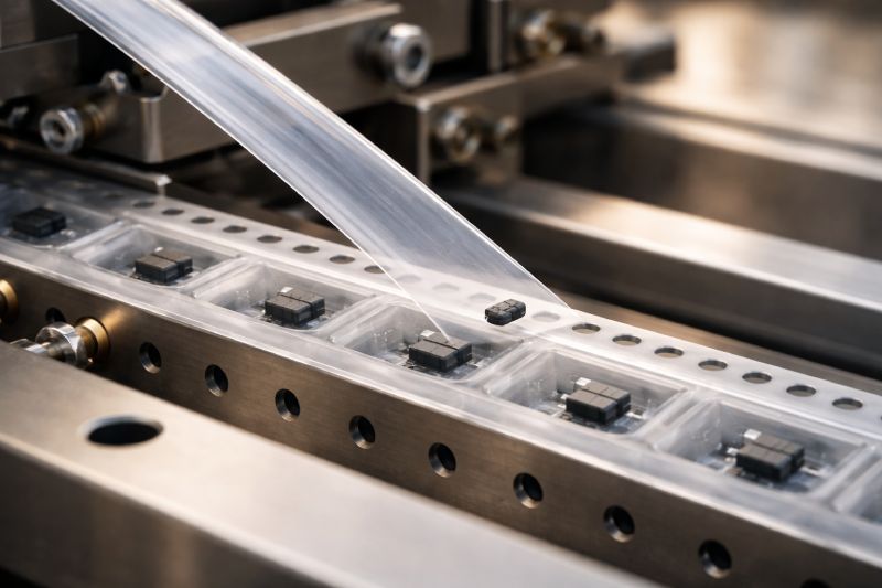
This creates an amplification effect.
Small variations in peel force translate into larger variations in release timing. Release timing variation leads to unpredictable component exposure relative to nozzle arrival. In high-speed placement, there is little tolerance for delay or premature release.
Additionally, dynamic inertia increases at higher speeds. Sudden energy release from peel separation can induce micro-vibrations within the pocket. These micro-movements may not be visible but can affect vacuum pickup stability.
At higher indexing speeds, even minor variations in peel force can create significant instability. For high-speed SMT lines, peel force consistency—not just average value—becomes a critical engineering control parameter.
Standard & Testing Considerations for Peel Force
Peel force testing is designed to simulate the separation behavior between cover tape and carrier tape under controlled conditions. However, the measured value is only meaningful when understood in context.
A typical peel test involves pulling the cover tape back at a defined angle—commonly around 165° or 180°—and at a constant speed. This provides a reference curve showing initial peak force, average peel force, and force stability along the seal line. The purpose of this test is not just to obtain a number, but to evaluate consistency and separation smoothness.
It is important to distinguish between static and dynamic testing. Static laboratory peel tests are performed at controlled speeds and stable conditions. In contrast, real SMT production introduces acceleration, vibration, and feeder motion. A peel force that appears stable in a static test may behave differently under dynamic feeding conditions.
Therefore, peel test values should be treated as reference indicators rather than absolute guarantees. System-level performance must also consider carrier tape design and dimensional control as defined in Carrier Tape Specifications, as well as tolerance consistency addressed in Carrier Tape Tolerance.
Ultimately, practical SMT performance carries more weight than isolated test numbers. Consistency under real operating conditions is the true evaluation standard.
Peel Force vs Component Type
Peel force sensitivity varies depending on component characteristics. The same peel condition that works well for one package type may create instability for another.
Lightweight components are highly sensitive to release energy. When peel separation occurs, even minor upward force or vibration can cause movement inside the pocket. For small passive devices or miniature LEDs used in LED Carrier Tape, controlled and consistent peel behavior is essential to prevent rotation or micro-shifting before pick-up.
Tall components present a different challenge. Their higher center of gravity increases susceptibility to tipping during release. If peel force produces sudden tension release, vertical instability may occur at the moment of exposure.
Fragile optical components—such as LEDs—are also sensitive to mechanical shock. Excessive peel energy can introduce subtle impact forces that affect surface integrity or orientation consistency.
For larger IC packages used in IC Carrier Tape, peel force stability remains important, but the risk profile shifts toward release timing synchronization rather than component escape. Heavier components may resist movement better, yet improper peel behavior can still reduce pick accuracy at high speeds.
Different component geometries, weights, and fragility levels respond differently to peel dynamics. Engineering evaluation should therefore align peel force control with the specific component type and application environment, rather than applying a universal approach.
How to Evaluate Peel Force in Your Application
Peel force evaluation should be based on application logic rather than fixed numerical targets. The correct approach depends on your SMT speed, component type, and carrier material selection.
If SMT speed is high, prioritize peel force consistency over absolute value. High indexing rates amplify even minor variations. A stable peel curve with minimal fluctuation is more important than achieving a specific average force.
If the component is lightweight or small, avoid excessively low peel force. Insufficient retention can allow micro-movement during transport and vibration. Stability during feeding must be confirmed under actual line speed conditions, not just laboratory testing.
If using PC carrier tape, carefully evaluate sealing parameters. PC’s higher rigidity changes how tension transfers during separation. Over-sealing may increase release energy, while under-sealing may reduce retention stability. Parameter matching between material and process is essential.
For tall or fragile components, observe release behavior using high-speed inspection if possible. Focus on timing synchronization between peel point and nozzle arrival.
Instead of asking, “What is the ideal peel force value?”, the more effective question is:
Does the peel behavior remain stable under my specific production conditions?
Application-based validation ensures peel force supports system stability rather than becoming an isolated test metric.
Peel Force Considerations in Custom Carrier Tape Projects
In custom carrier tape development, peel force should be validated early—during the sampling stage rather than after mass production begins. Custom pocket geometry, material selection, and component weight all influence how peel dynamics behave in real SMT conditions.
During prototyping for Custom Carrier Tape projects, sealing parameters must be tuned alongside material pairing. A change in pocket depth, corner radius, or wall stiffness can subtly affect how tension transfers during cover tape separation.
Consistency becomes even more critical in Custom Embossed Carrier Tape programs. Once mass production starts, even small deviations in sealing temperature, pressure, or dwell time can shift peel behavior across batches. Process repeatability is therefore as important as design optimization.
From a manufacturing perspective, peel force is not an isolated test item. It must be verified as part of a system that includes tooling precision, material compatibility, and controlled sealing conditions.
Successful custom projects treat peel force validation as a stability checkpoint—ensuring the final solution performs reliably under real SMT speed and environmental conditions.
Summary: Peel Force as a System Stability Parameter
Peel force is not a fixed material property—it is a dynamic process variable shaped by material pairing, sealing control, and operating conditions.
In high-speed SMT environments, its impact is amplified. Small fluctuations in peel behavior can translate into release instability, component movement, and placement variation.
For stable SMT performance, peel force must be evaluated as part of a complete system—including carrier tape material, pocket design, sealing parameters, component type, and feeder speed.
When treated as a system stability parameter rather than a standalone number, peel force becomes a controllable factor that supports consistent release timing and reliable placement yield.



 Emial
Emial John Mr


