








Embossed Carrier Tape: Design, Materials & SMT Applications Guide
What Is Embossed Carrier Tape?
Embossed carrier tape is a thermoformed plastic tape engineered to securely hold and transport electronic components during automated Surface Mount Technology (SMT) assembly. It features precisely formed cavities—known as pockets—that are shaped to match specific component geometries. These pockets prevent movement, rotation, and misalignment while the tape advances through high-speed pick-and-place equipment.
Unlike flat or punched alternatives, embossed carrier tape is formed through a controlled thermoforming process that creates three-dimensional pocket structures. This allows it to accommodate components with varying thicknesses, leads, and complex outlines.
In practical SMT production, embossed carrier tape functions as part of a complete tape-and-reel packaging system, which includes the carrier tape, a cover tape sealed on top, and a winding reel. Together, they enable consistent indexing, stable feeding, and accurate component presentation to the placement nozzle.
Embossed carrier tape is a thermoformed plastic tape with precisely formed pockets designed to secure and feed electronic components in automated SMT assembly.
Embossed Carrier Tape at a Glance
-
Available materials: Polycarbonate (PC), Polystyrene (PS), PET, including conductive and antistatic variants
-
Standard widths & pitch configurations: Multiple tape widths and pocket pitch options designed for SMT indexing systems
-
EIA-481 compliant: Compatible with global tape-and-reel dimensional standards
-
High-speed SMT ready: Designed for stable feeding in automated pick-and-place environments
-
Custom pocket structures available: Engineered solutions for non-standard or high-precision components
Embossed carrier tape operates as part of a complete tape and reel packaging system, ensuring components are presented consistently to SMT feeders. When properly specified, it supports stable indexing, controlled pocket geometry, and reliable high-speed automation.
For a deeper understanding of how the full packaging structure works together in SMT production, see our guide on tape and reel packaging for SMT assembly.
Why Embossed Carrier Tape Dominates Modern SMT Packaging
Modern SMT production lines operate at increasingly high indexing speeds, where mechanical stability and dimensional precision directly influence placement accuracy. Under these dynamic conditions, packaging becomes part of the process control system — not merely a transportation method.
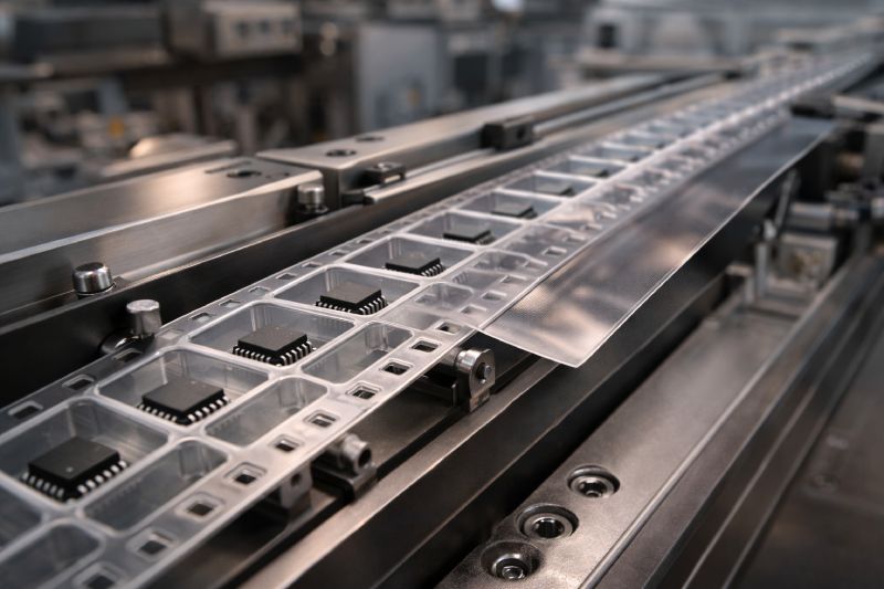
Embossed carrier tape supports high-speed automation by providing structurally defined pockets that maintain controlled component positioning. As component geometries become thinner, lighter, and more complex — including fine-pitch ICs and asymmetric packages — shallow or flat packaging solutions often lack sufficient positional stability.
High-speed feeders introduce acceleration forces, peel tension, and vibration. If pocket geometry, pitch alignment, or material rigidity are insufficient, feeding instability can occur. In such cases, issues may escalate into broader carrier tape failure in high-speed SMT environments, where cumulative tolerance deviation affects pickup consistency.
The structural depth and dimensional control enabled by thermoforming make embossed carrier tape suitable for modern automated assembly conditions.
Most importantly, embossed carrier tape enables precise positioning and stable feeding under high-speed automated conditions.
Standard Specifications of Embossed Carrier Tape
Embossed carrier tape follows standardized dimensional frameworks to ensure compatibility with global SMT feeder systems. These specifications are not arbitrary — they directly influence indexing accuracy, pickup positioning, and long-term feeding stability.
Rather than memorizing numbers, engineers must understand why each dimensional parameter matters within the SMT system.
Tape Width & Pitch Options
Tape width is selected based on component size and required lateral stability. Wider tapes provide structural rigidity for larger or taller components, while narrower formats are optimized for compact devices.
Pitch — the distance between consecutive pockets — determines synchronization with the feeder indexing mechanism. Even small pitch deviations can accumulate across long reels, affecting pickup alignment. A deeper explanation of how pitch impacts SMT accuracy can be found in our guide to carrier tape pitch and indexing stability.
Pocket Dimensions & Depth
Pocket length, width, and depth are engineered to balance controlled constraint with sufficient clearance.
If pockets are too shallow, components may tilt or protrude. If clearance is excessive, rotation risk increases during feeder acceleration. Depth stability also affects how components settle during vibration.
Pocket design therefore influences both mechanical retention and vision alignment reliability.
Sprocket Hole Alignment (D1)
Sprocket holes guide the tape through feeder pins. Their position relative to pocket centers determines indexing precision.
Misalignment between sprocket holes and cavity centers can lead to systematic pickup offset. Engineers evaluating feeder-related instability often examine D1 sprocket hole alignment tolerances to identify root causes.
EIA-481 Compatibility
Most embossed carrier tapes follow the EIA-481 dimensional standard. Compliance ensures mechanical compatibility across feeder systems and global SMT equipment.
Standardization reduces integration risk, simplifies multi-supplier sourcing, and provides a predictable baseline for dimensional validation.
In practice, specification control is less about checking a table — and more about understanding how dimensional stability supports placement accuracy under real production conditions.
How Embossed Carrier Tape Is Manufactured
The performance of embossed carrier tape begins at the manufacturing stage. Dimensional accuracy, pocket consistency, and long-term stability are determined by how precisely the thermoforming process is controlled. In high-speed SMT environments, even minor forming variations can influence feeding reliability.
Plastic Sheet Preparation
Production starts with carefully selected plastic sheets, typically PC, PS, or PET. Sheet thickness uniformity and internal stress distribution directly affect pocket depth consistency after forming.
Moisture control and material conditioning are critical. Variations at this stage may later manifest as camber, shrinkage differences, or wall thickness imbalance.
Heating & Thermoforming
The plastic sheet is heated to a controlled forming temperature where it becomes pliable without degrading structural integrity. It is then shaped through vacuum or pressure-assisted thermoforming using precision molds.
Temperature stability and forming pressure determine:
-
Wall thickness distribution
-
Corner radius clarity
-
Pocket depth accuracy
-
Surface finish consistency
Insufficient heat may cause incomplete forming, while excessive heat can result in thinning and dimensional drift.
For a detailed breakdown of how forming precision impacts final pocket geometry, refer to our guide on the carrier tape manufacturing process.
Precision Tooling
Tooling accuracy defines pocket repeatability across large production volumes. Mold alignment, machining precision, and cavity polishing directly influence tolerance control.
Any systematic deviation in tooling geometry may introduce cumulative pitch or center-offset variation, affecting SMT pickup consistency.
Cooling & Dimensional Stabilization
After forming, controlled cooling stabilizes the pocket geometry. Uneven cooling can create internal stress, leading to longitudinal curvature or dimensional drift over time.
Proper stabilization ensures that formed pockets retain their intended dimensions from production through reel winding and final feeder use.
Manufacturing precision ultimately determines pocket accuracy and tolerance stability. In embossed carrier tape engineering, process control is inseparable from performance reliability.
Key Design Factors That Affect Performance
Embossed carrier tape performance is determined by coordinated dimensional control, material behavior, and mechanical interaction with SMT equipment. Even when nominal specifications appear compliant, subtle geometric variations can influence pickup stability under dynamic conditions.
Understanding these factors requires looking beyond static measurements and evaluating system-level interaction.
Pocket Geometry & Component Fit
Pocket geometry must balance constraint and clearance. The goal is stable positioning without compression.
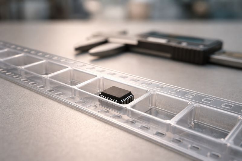
Key design elements include:
-
Side wall angle
-
Bottom flatness
-
Corner radius transition
-
Depth-to-width proportion
Excess lateral clearance increases the risk of component rotation during feeder acceleration. Insufficient clearance may lead to tilt or sticking during pickup.
Component rotation is not always a feeder issue; it often originates from subtle geometry imbalance. A deeper technical explanation can be found in our analysis of component rotation in carrier tape.
Pocket symmetry also influences how components settle during transportation vibration before entering the feeder.
Pitch Accuracy & Indexing Stability
Pitch accuracy defines how consistently each pocket aligns with feeder indexing increments.
Small pitch deviations may accumulate across long reels. When compounded with sprocket tolerance, pickup location may shift outside the acceptable placement window.
Stable pitch control depends on tooling precision, material shrinkage control, and consistent sprocket-to-pocket alignment.
Tolerance Stack-Up Effects
Carrier tape interacts with multiple system elements:
-
Feeder sprocket pins
-
Guide rails
-
Cover tape peel force
-
Reel tension
Each element carries manufacturing tolerance. When combined, these tolerances create a stack-up effect that may amplify small deviations.
For example, minor pocket center offset combined with feeder indexing variance may shift effective pickup position. Engineers evaluating this interaction often analyze overall carrier tape tolerance control rather than isolated dimensions.
System-level tolerance evaluation is essential in high-speed SMT production.
Interaction with Feeder Systems
Embossed carrier tape functions dynamically inside the feeder. During operation, it experiences:
-
Acceleration and deceleration forces
-
Peel tension from cover tape removal
-
Vertical lifting during pickup
-
Lateral guidance pressure
Material stiffness and pocket rigidity must withstand these forces without deformation. If pocket walls flex under peel stress, component seating stability may degrade.
Successful design anticipates real production conditions — not just laboratory measurements.
Embossed carrier tape must therefore be engineered as a mechanical interface within the SMT system, rather than as a passive packaging strip.
Materials Used in Embossed Carrier Tape
Material selection defines the structural limits and performance characteristics of embossed carrier tape. Although different materials may appear visually similar, their mechanical rigidity, forming behavior, and dimensional stability vary significantly under dynamic SMT conditions.
Material choice should therefore be aligned with process requirements — not simply cost considerations.
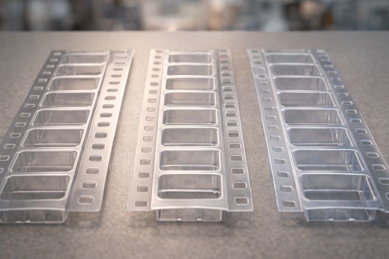
Polycarbonate (PC) — High Precision Stability
Polycarbonate is commonly used in high-speed or high-precision SMT environments due to its rigidity and dimensional stability.
Its structural stiffness helps maintain pocket geometry under feeder acceleration and peel force interaction. This makes it suitable for:
-
Fine-pitch ICs
-
Thin semiconductor packages
-
Yield-sensitive production lines
When dimensional stability is critical, many engineers evaluate PC carrier tape for high-precision SMT applications as a performance-focused option.
Polystyrene (PS) — Cost-Efficient Standard Solution
Polystyrene is widely used in standard SMT applications where moderate structural stability is sufficient.
It offers consistent thermoforming performance and controlled pocket replication at a competitive cost. Typical applications include:
-
Standard passive components
-
LEDs
-
Consumer electronics assemblies
PS provides reliable performance in mid-speed lines but may not offer the same rigidity margin as PC in high-acceleration environments.
PET — Balanced Structural Behavior
PET provides a balance between stiffness and flexibility. It offers improved crack resistance and stable forming behavior, making it suitable for applications requiring moderate mechanical durability.
In scenarios where environmental stability and forming consistency are both important, engineers often compare performance characteristics in a broader carrier tape materials comparison guide before final selection.
Conductive & Antistatic Variants — ESD Protection
For ESD-sensitive semiconductor components, conductive or antistatic material variants are required.
These materials control surface resistance to reduce electrostatic discharge risk during transport and feeding. Proper ESD material selection protects sensitive devices without compromising mechanical integrity.
Material selection in embossed carrier tape engineering is not a pricing variable — it defines mechanical behavior, tolerance stability, and system compatibility within the SMT process.
Applications of Embossed Carrier Tape
Embossed carrier tape is used across multiple SMT-driven industries where stable automated feeding and precise component positioning are essential. Its structural pocket design allows it to support diverse component geometries under high-speed production conditions.
Different application sectors impose different mechanical and tolerance demands on the tape system.
IC & Semiconductor Packaging
Integrated circuits and semiconductor devices often feature fine leads, thin profiles, and narrow placement tolerances. Even slight rotation or tilt can affect pickup alignment.
Embossed carrier tape provides controlled cavity geometry to maintain consistent orientation before vacuum pickup. For advanced packaging environments, engineers frequently evaluate IC carrier tape for SMT and semiconductor assembly to ensure pocket stability aligns with placement accuracy requirements.
LED Components
LED devices are typically lightweight and polarity-sensitive. Orientation control is critical for automated placement.
Structured pocket design minimizes micro-movement during indexing and peel interaction. Stable cavity geometry helps reduce rotation risk in high-speed lighting production lines, particularly in specialized LED carrier tape packaging configurations.
Automotive Electronics
Automotive SMT production requires enhanced reliability due to vibration exposure, temperature variation, and long service life expectations.
Embossed carrier tape used in this sector must maintain dimensional stability across extended production runs. Tolerance control becomes especially important for safety-critical modules and control units.
Precision Connectors
Miniature connectors often have asymmetric structures and fragile contact features.
Custom pocket geometry is frequently required to prevent deformation and ensure stable seating during feeder indexing. Proper constraint without compression is essential to protect delicate mechanical features.
Across these applications, embossed carrier tape functions as a mechanical interface between component packaging and automated placement systems — supporting consistent SMT performance across diverse manufacturing environments.
Embossed vs Punched Carrier Tape
Both embossed and punched carrier tapes are used in SMT packaging, but their structural capabilities and application ranges differ significantly.
Embossed carrier tape is thermoformed to create three-dimensional pockets with defined depth and wall geometry. This allows it to securely hold components with varying thicknesses, irregular outlines, or delicate leads. The formed cavity structure provides controlled lateral and vertical constraint under dynamic feeder conditions.
Punched carrier tape, by contrast, is typically produced by mechanically cutting cavities into flat material. The resulting pockets are generally shallower and structurally simpler. This format can be sufficient for flat, low-profile components that do not require deep containment or tight positional stability.
From an engineering perspective:
-
Complex geometries vs. simple shapes — Embossed tape supports irregular or thicker components; punched tape suits uniform, flat devices.
-
Deep pocket stability vs. shallow cavity retention — Embossed designs offer greater vertical constraint.
-
High-speed SMT adaptability — Embossed carrier tape performs more consistently under acceleration and peel interaction.
For a detailed technical breakdown of structural and application differences, see our guide on punched carrier tape in SMT packaging.
As component complexity and SMT speeds increase, embossed carrier tape typically provides the mechanical precision required for stable automated assembly.
Common Problems in Embossed Carrier Tape Applications
Even when embossed carrier tape meets dimensional standards, performance issues may still arise in real SMT production environments. These problems are rarely caused by a single parameter. Instead, they typically result from the interaction between pocket geometry, material behavior, feeder dynamics, and system-level tolerance accumulation.
Understanding why these issues occur is essential for accurate root cause analysis.
Pocket Deformation
Pocket deformation may originate during thermoforming, cooling, or feeder operation.
Uneven wall thickness, excessive forming stress, or insufficient material rigidity can reduce structural stability. Under acceleration or peel tension, weakened cavity walls may flex, altering component seating consistency.
Over long production runs, minor deformation effects can accumulate into measurable pickup variation.
Component Rotation
Component rotation is often linked to excessive lateral clearance or asymmetric pocket geometry.
When feeder indexing introduces vibration or acceleration forces, components with insufficient constraint may shift position. Lightweight or irregularly shaped devices are particularly sensitive to micro-movement within the cavity.
Engineers investigating such instability frequently analyze underlying causes related to carrier tape feeding problems, where geometric and dynamic factors intersect.
Feeding Instability
Feeding instability can appear as inconsistent indexing, pickup offset, or intermittent component presentation errors.
Pitch variation, sprocket-to-pocket misalignment, and tape camber may all contribute. These dimensional factors interact with feeder mechanics under dynamic conditions.
Because indexing behavior and peel interaction are closely linked, feeding stability is often evaluated together with parameters such as carrier tape peel force balance, which can influence mechanical stress during operation.
Peel Force Imbalance
During SMT operation, the cover tape is peeled at a controlled angle. If peel force is too high, it may introduce vertical or lateral stress on the carrier tape.
Excessive peel tension can distort pocket walls or slightly lift the tape from feeder rails. Conversely, insufficient peel force may compromise component retention during transportation.
Camber Issues
Camber refers to longitudinal curvature along the tape. It may result from internal stress generated during forming and cooling.
If stabilization is insufficient, the tape may not remain flat within the feeder, affecting sprocket engagement and indexing accuracy — particularly in high-speed assembly lines.
In most cases, embossed carrier tape problems are not isolated defects but manifestations of system-level interaction between geometry, material properties, and SMT dynamics.
When to Use Custom Embossed Carrier Tape
Standard embossed carrier tape configurations cover a wide range of SMT applications. However, certain production scenarios exceed the functional limits of standard pocket geometries and tolerance ranges. In these cases, custom embossed carrier tape becomes necessary to maintain yield stability and placement accuracy.
Custom solutions are typically required under the following conditions:
Non-standard component geometries
Components with irregular outlines, asymmetric mass distribution, fragile leads, or special orientation requirements often cannot be securely constrained within standard pocket designs. Custom tooling allows pocket walls, corner radii, and depth profiles to match the exact component geometry.
Tight tolerance requirements
High-precision SMT lines operating with narrow placement windows demand stricter pocket center alignment and dimensional repeatability. Custom tape can be engineered to minimize tolerance stack-up effects and improve indexing consistency.
High-speed SMT lines
As line speeds increase, dynamic forces during acceleration and cover tape peeling intensify. Custom structural reinforcement, optimized draft angles, and refined clearance control may be necessary to maintain feeding stability.
Yield-critical production environments
In automotive, semiconductor, or high-reliability electronics manufacturing, even small feeding inconsistencies can impact overall yield. Custom embossed carrier tape supports risk reduction in these sensitive production contexts.
When standard specifications no longer provide sufficient mechanical stability or dimensional control, custom-engineered embossed carrier tape offers a solution aligned with system-level SMT performance requirements.
Engineering Checklist Before Choosing Embossed Carrier Tape
Selecting embossed carrier tape should be treated as an engineering decision rather than a simple purchasing task. The tape interacts dynamically with components, feeders, cover tape, and placement systems. Evaluating the following factors helps ensure compatibility and long-term production stability.
1. Component Geometry Complexity
-
Does the component have irregular edges, leads, or asymmetrical mass distribution?
-
Is orientation control critical for placement accuracy?
-
Are there fragile structures that require controlled clearance rather than tight compression?
Complex geometries often require refined pocket wall design and depth optimization.
2. SMT Line Speed
-
What is the indexing speed of the feeder system?
-
Does the production line operate under high acceleration and deceleration cycles?
Higher speeds increase dynamic stress on both pocket walls and component seating stability. Material rigidity and pitch accuracy become more critical under these conditions.
3. Required Placement Accuracy
-
What is the acceptable pickup positional tolerance?
-
How narrow is the placement window in the vision alignment system?
Tight placement accuracy demands strict pocket center alignment relative to sprocket indexing and controlled dimensional consistency across the reel.
4. Cost Constraints
-
Is the application cost-sensitive or yield-sensitive?
-
Does reduced material cost justify potential increases in feeding variability?
Material choice should align with performance demands, not solely price considerations.
5. Material Compatibility & ESD Requirements
-
Is the component sensitive to electrostatic discharge?
-
Does the production environment require conductive or antistatic material variants?
Surface resistance control may be necessary to protect semiconductor devices during transport and feeding.
By evaluating embossed carrier tape against these engineering criteria, decision-makers can ensure that packaging design supports SMT performance rather than introducing hidden variability into the production process.
FAQs About Embossed Carrier Tape
What is embossed carrier tape used for?
Embossed carrier tape is used to securely hold and feed electronic components during automated SMT assembly. It organizes components in precisely formed pockets, allowing consistent indexing and accurate pickup by high-speed pick-and-place machines. It is widely used for ICs, LEDs, connectors, and other surface-mount devices.
Is embossed carrier tape better than punched tape?
Embossed carrier tape is generally better suited for complex, thick, or precision components because it provides deeper and more structurally defined pockets. Punched tape may be adequate for simple, flat components. The choice depends on component geometry, SMT speed, and required placement accuracy rather than a universal superiority.
What material is best for embossed carrier tape?
There is no single “best” material. Polycarbonate (PC) is preferred for high-precision and high-speed applications due to its rigidity. Polystyrene (PS) is cost-efficient for standard components. PET offers balanced performance. The optimal material depends on mechanical stability requirements and ESD sensitivity.
What is the difference between embossed and thermoformed carrier tape?
In most contexts, embossed carrier tape is produced through a thermoforming process. “Thermoformed” describes the manufacturing method, while “embossed” refers to the formed pocket structure. Practically, embossed carrier tape is a type of thermoformed carrier tape designed for SMT packaging.
Does embossed carrier tape affect SMT yield?
Yes. Pocket geometry accuracy, pitch stability, material rigidity, and peel interaction all influence component positioning during pickup. Variations in these factors can contribute to rotation, misalignment, or feeding inconsistency, which may impact placement accuracy and overall production yield.
Summary: Embossed Carrier Tape as a System-Level Engineering Solution
Embossed carrier tape is not merely a packaging material used to transport components. It is a precision-engineered interface between electronic devices and automated SMT assembly systems.
Its pocket geometry, material behavior, pitch accuracy, and interaction with feeder dynamics directly influence placement stability and production yield. From manufacturing process control to system-level tolerance management, every parameter contributes to overall SMT performance.
When properly engineered and selected based on real production conditions, embossed carrier tape supports reliable high-speed feeding, controlled component positioning, and consistent assembly accuracy.
In modern electronics manufacturing, embossed carrier tape should be evaluated not as a commodity — but as an integral part of the SMT precision system.



 Emial
Emial John Mr


