








How to Inspect Carrier Tape Before SMT Production | Engineering Guide
Why Carrier Tape Inspection Matters Before SMT
Surface Mount Technology (SMT) is a high-speed, highly automated manufacturing system. Modern pick-and-place machines operate at extreme indexing speeds, where even minor positional deviations can translate into measurable placement errors. In this environment, carrier tape is not just packaging — it is a precision feeding component that directly affects component positioning accuracy.
The carrier tape controls how components are presented to the feeder, how consistently they index forward, and how reliably each pocket aligns with the pick-up nozzle. If the tape geometry, pitch, or sprocket hole alignment deviates — even slightly — the feeder system will replicate and amplify that deviation across thousands of placements per hour.
Uninspected carrier tape introduces hidden risks. A small dimensional inconsistency that appears negligible in static measurement can become a placement offset under dynamic feeding conditions.
Core engineering principle:
Small dimensional deviations in carrier tape can become placement errors in high-speed SMT.
This is why structured inspection must precede production loading — especially when tolerances, pitch stability, or feeding reliability are critical. For deeper understanding, see related topics such as Carrier Tape Tolerance and Carrier Tape Feeding Issues, which explain how small deviations propagate through the SMT process.
When Should Carrier Tape Be Inspected?
Carrier tape inspection should not be treated as a routine formality. It is a risk-triggered engineering decision. Certain production scenarios significantly increase the probability that dimensional variation, forming instability, or material differences could affect SMT performance.
Inspection is strongly recommended in the following situations:
1. New Supplier Introduction
When sourcing carrier tape from a new supplier, process stability and tooling accuracy are not yet validated within your production environment. Even if specifications appear compliant, forming methods, raw material batches, and tooling wear conditions may differ.
2. First Article Production (FAI Stage)
Before mass production, first-article inspection confirms that pocket geometry, pitch consistency, and cover tape compatibility align with feeder requirements. This stage prevents systematic deviation from entering volume manufacturing.
3. Custom Carrier Tape Projects
Custom pocket designs introduce new variables — cavity depth, corner radius, material selection, and forming parameters. Without inspection, design assumptions remain unverified under real-world conditions.
4. High-Speed SMT Lines
The faster the indexing speed, the smaller the tolerance window becomes. High-speed machines amplify feeding inconsistencies more aggressively than low-speed systems.
5. Yield-Sensitive or Precision Assemblies
In applications such as fine-pitch components, miniature packages, or high-density PCB layouts, even minor pickup offsets can reduce yield.
In short, inspection should be triggered whenever process risk increases. Waiting until placement defects appear on the line is already too late — inspection belongs at the prevention stage, not the correction stage.
Step 1: Visual Inspection of Carrier Tape
Visual inspection is the first and fastest screening method before any dimensional measurement is performed. Although it may appear basic, visual anomalies often indicate deeper forming or material control issues. Many dimensional problems first manifest as subtle surface or structural irregularities.
Visual inspection should be conducted under stable lighting conditions, ideally using magnification when necessary. The goal is not only to identify obvious defects, but also to detect early signs of forming instability.
Pocket Integrity
The pocket is the functional core of the carrier tape. Each cavity must maintain consistent geometry and structural stability.
Inspect for:
-
Deformation – Warped or partially collapsed pocket walls can reduce component seating stability.
-
Burrs or sharp edges – Improper trimming or forming defects may create micro-burrs that interfere with component placement or cover tape sealing.
-
Uneven forming depth – Inconsistent cavity depth across consecutive pockets may indicate forming pressure fluctuation or tooling wear.
Pocket symmetry is especially important. Even slight asymmetry can shift the component’s resting position inside the cavity, increasing the probability of pick-up offset during feeding.
Surface Defects
The tape surface condition directly affects both mechanical feeding and cover tape adhesion.
Check for:
-
Scratches or drag marks – These may signal material handling issues during forming or slitting.
-
Contamination or debris – Dust, plastic fragments, or oil residue can interfere with peel consistency and component stability.
-
Uneven color or surface gloss variation – This can indicate material inconsistency between batches or improper heating during thermoforming.
Surface irregularities are rarely isolated cosmetic problems. They often reflect upstream process instability.
Sprocket Hole Alignment
Sprocket holes drive indexing accuracy. Any irregularity here directly affects feeding precision.
Visually examine:
-
Hole roundness
-
Edge cleanliness
-
Alignment consistency along the tape length
Irregular hole geometry may lead to uneven engagement with feeder pins, increasing indexing deviation.
Important engineering insight:
Visual defects frequently signal process-level instability. Early detection at this stage prevents defective tape from advancing into dimensional inspection or — worse — into live SMT production.
Step 2: Dimensional Inspection
Dimensional inspection is the most critical phase of carrier tape verification before SMT production. While visual checks identify obvious forming defects, dimensional control determines whether the tape will maintain positional stability during high-speed indexing.
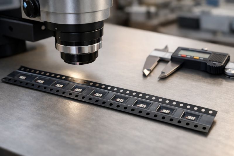
Carrier tape functions as a mechanical guidance system inside the feeder. Its geometry governs how accurately each component is presented to the pick-up nozzle. Therefore, dimensional inspection must focus not only on nominal compliance, but on consistency across multiple pockets.
A single measurement is never sufficient. Variation trends matter more than isolated readings.
Measuring Pocket Width & Depth
Pocket width and depth directly affect how the component sits inside the cavity. Excess lateral clearance may allow component rotation. Insufficient depth can cause partial exposure above the pocket plane.
During inspection:
-
Measure multiple consecutive pockets.
-
Compare variation across the sample range.
-
Observe consistency rather than relying on one central pocket.
Inconsistent forming depth across the tape often indicates unstable thermoforming parameters or tooling wear. Even small depth fluctuation can alter pick height consistency during automated pickup.
Checking Pitch Consistency
Pitch refers to the center-to-center distance between adjacent pockets. It must remain stable along the tape length to ensure correct synchronization with feeder indexing.
Key inspection principles:
-
Measure across multiple pitch intervals.
-
Evaluate cumulative spacing over several pockets.
-
Detect progressive drift patterns.
Pitch drift is more dangerous than a one-time deviation because it accumulates during feeding. Over time, small spacing variation can create systematic pick misalignment.
For deeper understanding of pitch behavior and its effect on feeding precision, refer to Carrier Tape Pitch.
Verifying Tape Width
Tape width ensures proper alignment within feeder guide rails. Even minor width variation can influence lateral positioning.
Inspection should confirm:
-
Uniform width across the entire sample.
-
No edge waviness or slitting irregularities.
-
Stable relationship between tape edges and pocket centers.
Tape width variation can create subtle lateral shifts during feeding, particularly in high-speed SMT environments.
More details can be found in Carrier Tape Dimensions, which explains structural dimensional control principles.
Inspecting D1 Hole Position
The D1 hole is a critical indexing reference point. Its position relative to the pocket center must remain consistent to maintain accurate pick timing.
Inspection focus:
-
Relative alignment between hole center and pocket center.
-
Consistency across multiple holes.
-
Absence of eccentric forming or oval distortion.
Misaligned D1 holes may not cause immediate visible defects, but they introduce synchronization errors inside the feeder system.
For detailed structural explanation, see Carrier Tape D1 Hole.
Engineering principle to remember:
Single-point measurement is not enough.
Dimensional stability must be verified across multiple pockets to ensure repeatability under dynamic SMT feeding conditions.
Step 3: Tolerance Verification & Deviation Pattern Analysis
Dimensional measurement alone is not sufficient. The next engineering step is to interpret those measurements correctly. Tolerance verification is not just about checking whether a value falls within an acceptable range — it is about understanding how deviations behave across the tape.
In practice, two tapes may both appear “within tolerance,” yet perform very differently in SMT production. The difference lies in deviation pattern.
Nominal vs. Actual Measurement
Every carrier tape design begins with nominal dimensions — theoretical design values defined during tooling development. Inspection compares actual measurements against these nominal targets.
However, the critical question is not simply:
“Is this value acceptable?”
The real question is:
“How stable is this value across the sample length?”
A tape that consistently measures slightly offset but stable may behave more predictably than a tape that fluctuates randomly around the nominal dimension.
Variation Trend Analysis
Engineers should review:
-
Measurement progression across consecutive pockets
-
Repeating deviation intervals
-
Gradual drift over tape length
A gradual dimensional shift (for example, progressive pitch variation) indicates forming parameter instability or material stretch behavior. This type of trend can cause cumulative indexing misalignment.
Trend analysis helps identify whether variation is isolated or structural.
Systematic vs. Random Deviation
Understanding deviation type is essential:
Systematic deviation
-
Repeats consistently
-
Often linked to tooling alignment or calibration offset
-
Affects every pocket similarly
This type of deviation is more dangerous because it produces predictable but amplified placement shift in high-speed SMT.
Random deviation
-
Irregular fluctuation
-
Often linked to material instability or inconsistent forming pressure
-
Harder to predict but usually less accumulative
While both types require correction, systematic deviation poses higher risk in dynamic feeding environments because the feeder will replicate the error continuously.
Key engineering insight:
A single pocket slightly out of tolerance may not cause failure.
A consistent deviation pattern across hundreds of pockets almost certainly will.
Carrier tape inspection must therefore move beyond pass/fail evaluation and into deviation behavior analysis. This is what separates basic quality checking from true engineering risk control.
Step 4: Peel Force & Cover Tape Compatibility Check
Carrier tape inspection is incomplete without evaluating the interaction between the carrier tape and its cover tape. In SMT production, component stability depends not only on pocket geometry but also on how consistently the cover tape seals and peels during feeding.
Peel behavior is a dynamic parameter. It directly affects component retention before pickup and release stability during indexing.
Peel Consistency
Inspection should verify:
-
Smooth and continuous peel behavior
-
No sudden force spikes
-
No intermittent sticking or tearing
Peel consistency ensures that the cover tape separates predictably from the carrier tape at the designated peel angle inside the feeder. Inconsistent peel can introduce vibration or sudden release motion, disturbing component seating just before pickup.
Excessive Peel Force
If peel force is too high:
-
The feeder motor may experience additional resistance
-
Sudden release tension may cause tape jerk
-
Component shift inside the pocket may occur
Excessive peel force is often linked to material incompatibility, sealing temperature instability, or improper adhesive formulation.
Low Peel Force & Component Jump Risk
If peel force is too low:
-
Cover tape may lift prematurely
-
Components may shift or jump under vibration
-
Dust contamination risk increases
Low retention strength reduces component stability during transport and feeding.
Important engineering principle:
Cover tape inspection is part of carrier tape inspection. The two function as a mechanical system, not independent materials.
Proper compatibility verification ensures that sealing performance, peel behavior, and pocket retention work together under real SMT conditions. For further understanding, refer to Cover Tape for Carrier Tape. A more detailed engineering analysis of peel mechanics can be explored in a dedicated Carrier Tape Peel Force Guide.
Step 5: Feeding Simulation or Feeder Test
Static inspection provides critical geometric and structural validation — but it does not fully represent real SMT operating conditions. Carrier tape performs inside a dynamic system, where acceleration, indexing speed, vibration, and peel motion interact simultaneously.
This is why a feeding simulation or controlled feeder test is strongly recommended before full-scale production.
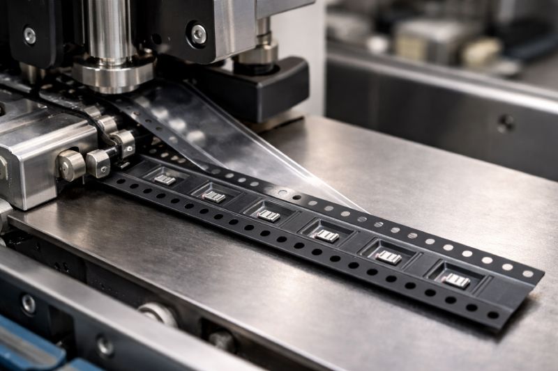
Dummy Feeder Run
A dummy run involves loading the carrier tape into a feeder without live PCB placement. The purpose is to observe mechanical behavior under indexing motion.
Engineers should monitor:
-
Smooth advancement of tape
-
Stable engagement of sprocket holes
-
Absence of skipping or micro-jumping
-
Consistent peel progression
This step helps reveal mechanical resistance or alignment instability that may not be visible during bench inspection.
Short Trial Production Run
For higher-risk or custom projects, a short controlled SMT trial is advisable.
During the trial, observe:
-
Pickup consistency
-
Nozzle alignment stability
-
Component centering after placement
-
Any increase in feeder alarm frequency
Dynamic feeding conditions often expose issues such as cumulative pitch drift, micro-lateral shifting, or inconsistent peel release that static measurement cannot fully simulate.
Why Static Inspection Is Not Enough
A carrier tape may pass visual and dimensional inspection but still behave unpredictably under high-speed indexing. Dynamic forces amplify:
-
Minor geometric variation
-
Peel force fluctuation
-
Material stiffness differences
High-speed SMT systems magnify small inconsistencies through repeated mechanical cycling.
Engineering conclusion:
Static inspection verifies structure.
Feeder simulation verifies behavior.
Only when both are validated can carrier tape be confidently released for production use.
Common Carrier Tape Defects Detected During Inspection
Structured inspection often reveals recurring defect patterns that directly affect SMT feeding stability. These defects are rarely random — they usually originate from tooling wear, material instability, or forming parameter fluctuation.
Understanding typical defect types helps engineers trace root causes more efficiently.
Pitch Drift
Pitch drift refers to gradual spacing variation between consecutive pockets. Instead of a uniform center-to-center distance, the spacing slowly shifts along the tape length.
This condition commonly results from:
-
Thermoforming tension imbalance
-
Material stretch during forming
-
Feed roller calibration issues
Pitch drift is particularly dangerous because it accumulates. Even a small progressive deviation can create feeder indexing misalignment over time.
Pocket Asymmetry
Pocket asymmetry occurs when one side of the cavity forms slightly differently than the other. The cavity may appear visually acceptable, yet the internal geometry is not centered.
Common causes include:
-
Uneven forming pressure
-
Tool misalignment
-
Partial mold wear
Asymmetry increases the risk of component tilt or lateral resting shift, especially for small passive components.
Hole Eccentricity
Sprocket hole eccentricity means the hole center does not align consistently with the intended reference position.
This typically stems from:
-
Punching tool wear
-
Die alignment deviation
-
Progressive tool clearance change
Even minor eccentricity can disturb feeder pin engagement, increasing indexing variation.
Inconsistent Forming Depth
Variation in cavity depth across multiple pockets is another frequent issue.
Possible causes:
-
Heating inconsistency
-
Material thickness fluctuation
-
Forming pressure instability
Depth inconsistency affects pickup height uniformity and can influence nozzle vacuum performance.
Engineering insight:
Most carrier tape defects originate upstream — in tooling condition, material control, or forming process stability.
Inspection is not only about identifying defects. It also serves as an early diagnostic tool to evaluate manufacturing process health before issues propagate into SMT production.
Inspection Tools & Equipment Used for Carrier Tape
Effective carrier tape inspection requires appropriate measurement and verification tools. While advanced systems can improve efficiency, even basic instruments — when used correctly — can provide reliable engineering insight.
The key is not brand or automation level, but measurement method and consistency.
Digital Caliper
A digital caliper is commonly used for:
-
Measuring overall tape width
-
Verifying pocket width at reference points
-
Checking cumulative pitch across multiple pockets
Although simple, calipers should be applied carefully to avoid compressing the material during measurement. Multiple readings across different sections of the tape are recommended to detect variation trends.
Optical Measuring Microscope
An optical measuring microscope allows more precise observation of:
-
Pocket geometry and corner integrity
-
Relative alignment between pocket center and sprocket hole
-
D1 hole position accuracy
Magnification enables engineers to detect subtle deformation or eccentricity that may not be visible to the naked eye.
Vision Inspection System
For higher-volume environments or critical projects, automated vision systems can:
-
Capture dimensional data across long tape sections
-
Detect deviation patterns
-
Analyze pitch consistency and alignment stability
Vision-based inspection improves repeatability and reduces subjective interpretation.
Peel Force Tester
A peel force tester measures the mechanical behavior of cover tape separation. It evaluates:
-
Peel consistency
-
Force stability during separation
-
Sudden release spikes
Since peel performance directly influences feeding stability, this tool is essential when cover tape compatibility is critical.
Engineering reminder:
Inspection tools provide data.
Engineering judgment interprets that data.
Regardless of equipment level, structured measurement, multi-point verification, and deviation trend analysis remain the foundation of reliable carrier tape inspection.
How Inspection Results Affect SMT Stability
Carrier tape inspection is not an isolated quality procedure. Its findings directly influence SMT line stability, placement accuracy, and overall production yield. To understand this impact clearly, it is useful to view inspection results through an engineering cause-and-effect chain.
From Inspection Issue to Yield Loss
A typical risk progression may look like this:
Dimensional or structural deviation detected (or undetected)
→ Feeder indexing deviation
→ Pick position shift
→ Placement accuracy loss
→ Increased rework or yield reduction
Each step amplifies the previous one.
For example, a slight pitch inconsistency may appear insignificant during manual measurement. However, once loaded into a high-speed feeder, cumulative indexing deviation can shift component presentation timing. The nozzle may pick slightly off-center, leading to marginal placement offset. Repeated thousands of times, this deviation affects solder joint reliability and increases defect rates.
Dynamic Systems Magnify Small Errors
SMT is a repetitive, high-frequency mechanical system. What appears as a minor deviation in static inspection can become:
-
Consistent pickup height variation
-
Micro-lateral shift during indexing
-
Increased feeder alarm frequency
-
Reduced placement repeatability
Because SMT operates at speed, small dimensional inconsistencies are not isolated events — they are repeated continuously.
Stability Is a System-Level Outcome
Carrier tape, cover tape, feeder mechanics, and placement head accuracy work together as one system. Inspection results help ensure that the carrier tape component of this system does not introduce instability.
If inspection identifies deviation trends early, corrective action can be taken before production loading. If inspection is skipped, the system itself becomes the diagnostic tool — often at the cost of downtime and yield loss.
Engineering conclusion:
Inspection findings are not paperwork.
They directly determine feeding precision, placement stability, and production performance.
In high-speed SMT environments, prevention is always less expensive than correction.
Inspection Considerations for Custom Carrier Tape Projects
Custom carrier tape projects introduce additional engineering variables that make inspection even more critical. Unlike standard tape formats, custom designs involve new pocket geometries, material selections, and forming parameters that have not yet been validated under real production conditions.
For this reason, first-article inspection is not optional — it is mandatory.
Why First-Article Inspection Is Essential
During initial production of a custom carrier tape:
-
Tooling is newly calibrated
-
Forming parameters are still being optimized
-
Material behavior under heat and pressure may vary
Even if the design drawings are correct, actual forming results may differ slightly. First-article inspection verifies whether the manufactured tape truly reflects the intended geometry and alignment.
Tolerance Validation Under Real Conditions
Custom designs often push tolerance boundaries — especially for miniature or irregular-shaped components. Inspection must confirm:
-
Pocket stability and symmetry
-
Consistent pitch across sample length
-
Accurate hole-to-pocket positional relationship
Nominal design approval alone does not guarantee feeder compatibility.
Material and Design Joint Verification
Custom projects often involve specific material requirements such as anti-static properties, higher stiffness, or deeper cavity depth. Inspection should confirm that material performance and geometric design function together properly.
For further structural understanding, see related topics such as Custom Carrier Tape and the Carrier Tape Design Guide, which explain how pocket geometry and material selection interact in engineered tape solutions.
Engineering principle:
Custom design increases flexibility — but also increases risk.
Structured inspection ensures that new designs are validated before entering high-speed SMT production, protecting both placement accuracy and overall yield stability.
Final Inspection Checklist Before SMT Production
Before releasing carrier tape to the SMT line, a structured final verification ensures that no critical step has been overlooked. The goal is not to repeat every measurement, but to confirm that all key risk areas have been evaluated.
Below is a practical pre-production checklist:
-
Visual inspection completed
Pocket integrity verified, no deformation, burrs, or surface contamination detected. -
Dimensional inspection performed
Pocket geometry, pitch consistency, tape width, and hole positioning checked across multiple pockets. -
Tolerance trend reviewed
No systematic deviation or progressive drift observed in measurement data. -
Peel force tested
Cover tape compatibility confirmed, peel behavior stable and consistent. -
Feeder simulation or trial run conducted
Tape advances smoothly, no skipping, misalignment, or abnormal vibration detected.
This checklist helps ensure that carrier tape performance has been validated from both structural and dynamic perspectives.
In high-speed SMT environments, verification before loading is far more efficient than troubleshooting after defects appear. Structured inspection turns potential risks into controlled variables — before production begins.
Summary: Inspection as Risk Prevention, Not Formality
Carrier tape inspection before SMT production is not a paperwork exercise — it is a risk control mechanism.
SMT systems operate at high speed and high repetition. In such dynamic environments, small dimensional deviations, subtle peel inconsistencies, or minor alignment shifts do not remain small. They are amplified through continuous indexing and repeated pickup cycles.
Structured inspection achieves three critical objectives:
-
It identifies geometric instability before loading.
-
It detects deviation patterns that could affect feeder synchronization.
-
It prevents avoidable yield loss, downtime, and troubleshooting costs.
When inspection is treated as a preventive engineering step rather than a procedural formality, it becomes a powerful stability safeguard.
In high-speed SMT production, the cost of prevention is always lower than the cost of correction.



 Emial
Emial John Mr


