








Carrier Tape Testing Methods: Complete SMT Quality Control Guide
What Is Carrier Tape Testing?
Carrier tape testing refers to the inspection and verification procedures used to ensure dimensional accuracy, material consistency, and compatibility with SMT feeder systems. It is a structured quality control process applied to embossed or punched carrier tape before it enters high-speed surface mount production.
In many factories, carrier tape inspection is mistakenly reduced to simple dimensional checks—measuring pocket width, depth, or pitch. However, carrier tape testing goes beyond basic measurement. It evaluates how the tape performs mechanically and dynamically under real feeding conditions, including cover tape release behavior and indexing stability.
The true objective of SMT carrier tape testing is not only to confirm that the tape meets drawing specifications, but to ensure:
-
Stable indexing in feeder systems
-
Controlled component retention during transport
-
Accurate pick alignment during vacuum pickup
-
Consistent placement yield on PCB assembly lines
In engineering terms, carrier tape testing serves as a preventive control mechanism. It verifies that the tape will not introduce instability into automated assembly, where even micron-level deviations can escalate into placement errors.
In summary: Carrier tape testing is the systematic evaluation of dimensional precision, material behavior, and feeder compatibility to ensure stable feeding and accurate component placement in SMT production.
Why Carrier Tape Testing Matters in High-Speed SMT
In modern high-speed SMT production, small mechanical deviations can become amplified into measurable yield losses. As placement speeds increase and component sizes shrink, the tolerance window narrows dramatically. What may appear acceptable under static inspection can become unstable during dynamic feeder indexing.
High-speed machines index carrier tape hundreds of times per minute. Under these conditions, minor variations in pocket geometry, pitch spacing, or material rigidity can lead to:
-
Inconsistent component centering
-
Micro-rotation inside pockets
-
Indexing drift over cumulative length
-
Increased pick vacuum compensation
-
Placement misalignment
The engineering cause-and-effect chain typically follows this pattern:
Tolerance deviation
→ Indexing error
→ Pick misalignment
→ Placement yield loss
In other words, carrier tape testing is not simply about confirming specification compliance. It functions as a risk control mechanism within the broader SMT process.
For example:
-
A slight cumulative pitch error may not be noticeable across a few pockets, but over hundreds of indexes, it can shift pick positions outside machine compensation limits.
-
Insufficient material rigidity may allow pocket deformation under feeder tension, affecting component seating stability.
-
Inconsistent peel behavior can introduce vibration or component bounce during release.
As SMT lines operate at higher speeds—particularly in consumer electronics, automotive electronics, and miniaturized PCB assemblies—carrier tape testing becomes a system-level stability safeguard.
It is important to understand:
Testing is not performed to “pass inspection.”
It is performed to prevent downstream instability.
In high-speed SMT environments, carrier tape is not just packaging—it is a mechanical interface between the component and the placement machine. Ensuring its stability through structured testing directly protects placement accuracy and overall production yield.
Key Categories of Carrier Tape Testing
Carrier tape testing methods can be grouped into four primary engineering categories. Each category targets a different risk factor within SMT production. A complete carrier tape inspection system should address all four areas, rather than focusing on dimensions alone.
Dimensional Testing
Dimensional testing verifies whether the carrier tape meets geometric specifications required for precise indexing and component positioning.
Key inspection parameters include:
-
Pocket width and depth – Ensures proper component fit without excessive lateral movement or compression.
-
Pocket pitch – Confirms consistent spacing between pockets to maintain indexing accuracy.
-
Sprocket hole position and diameter – Critical for feeder engagement and step consistency.
-
Overall tape width – Ensures compatibility with feeder guide rails and tension systems.
Dimensional errors can accumulate over length. Therefore, both single-point measurement and cumulative pitch evaluation are essential.
Mechanical Performance Testing
Mechanical testing evaluates how the tape behaves under stress and dynamic loading conditions.
Typical focus areas include:
-
Rigidity and stiffness – Determines resistance to bending or warping inside feeder tracks.
-
Pocket structural stability – Ensures cavities maintain geometry during transportation and handling.
-
Deformation resistance – Assesses how material reacts to tension, compression, and temperature changes.
Material selection (PS, PET, PC) significantly affects mechanical behavior, especially in high-speed applications.
Cover Tape & Peel Force Testing
This category examines the interaction between the carrier tape and the cover tape.
Key aspects include:
-
Peel consistency – Ensures uniform release force throughout the reel.
-
Release stability – Prevents sudden jerks or vibration during cover separation.
-
Component retention before peel – Confirms secure sealing during shipping and storage.
Peel instability can directly affect feeding smoothness and component pick reliability.
Functional Feeding Testing
Functional testing simulates real SMT operating conditions to validate overall system compatibility.
This includes:
-
Feeder compatibility verification
-
Dynamic indexing observation
-
Component movement monitoring during peel and pick
-
High-speed simulation under realistic tension conditions
Static measurement confirms compliance.
Functional feeding testing confirms real-world stability.
A comprehensive carrier tape testing program integrates all four categories to ensure dimensional precision, mechanical reliability, peel consistency, and dynamic feeding performance. Only by evaluating the tape as a system component—not just a packaging material—can SMT stability be fully protected.
Dimensional Testing Methods Explained
Dimensional testing is the foundation of carrier tape inspection methods. However, effective dimensional control requires more than checking a few sample points. The goal is to understand both localized deviations and cumulative tolerance behavior across the full reel length.
Optical Measurement Systems
Modern carrier tape testing often relies on optical measurement systems. These include:
-
High-resolution vision inspection platforms
-
Profile projectors
-
2D or 3D optical scanners
Optical systems allow non-contact measurement of:
-
Pocket width and depth
-
Pocket center location
-
Sprocket hole diameter and position
-
Pocket-to-hole alignment
Non-contact inspection is especially important for thin-wall embossed tapes, where mechanical probes may introduce deformation during measurement.
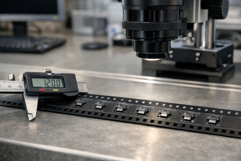
Digital Caliper & Microscope Verification
For smaller batch production or custom tape validation, manual verification tools are commonly used:
-
Digital calipers for overall tape width and pitch spot-checking
-
Measuring microscopes for pocket geometry confirmation
-
Cross-section observation for depth consistency
While manual methods are effective for verification, they must be performed carefully to avoid compressing the material. Measurement pressure itself can distort flexible tapes, leading to inaccurate readings.
Automated Inline Inspection Systems
In high-volume production, automated inspection systems monitor dimensional consistency during embossing or punching processes.
These systems:
-
Track pitch accuracy in real time
-
Detect pocket deformation
-
Identify hole position drift
-
Flag cumulative alignment shifts
Inline systems help prevent batch-level deviations before reels are completed.
Single-Point Error vs. Cumulative Error
A critical concept in carrier tape dimensional testing is the difference between single-point error and cumulative error.
-
Single-point error refers to a deviation in one pocket or hole.
-
Cumulative error refers to progressive drift across multiple pitches.
Even if individual pockets remain within tolerance, small pitch variations can accumulate. Over hundreds of indexes, this may result in feeder misalignment beyond machine compensation limits.
This phenomenon is known as tolerance stack-up.
Effective carrier tape testing therefore includes:
-
Multi-point pitch measurement
-
Long-distance cumulative verification
-
Pocket-to-sprocket alignment analysis
Dimensional compliance at isolated points does not guarantee indexing stability across the entire reel.
In summary, dimensional testing is not simply about checking numbers against a drawing. It is about verifying geometric consistency across length, understanding tolerance accumulation behavior, and ensuring that dimensional variation will not translate into feeding instability in SMT production.
Peel Force Testing: Why It’s Critical
Peel force testing evaluates the release behavior between the carrier tape and the cover tape during component feeding. While often underestimated, peel performance is one of the most critical dynamic parameters in SMT carrier tape testing.
Peel force refers to the resistance encountered when the cover tape separates from the carrier tape during feeder operation. Unlike static dimensional parameters, peel behavior is a dynamic interaction that directly affects feeding smoothness and component stability.
When Peel Force Is Too High
If peel resistance is excessive:
-
Feeder motors experience increased load
-
Sudden release events can occur
-
Vibration may transfer into the pocket
-
Components may bounce or shift before pickup
High peel force can introduce micro-instability precisely at the moment when the component is exposed for vacuum pick-up.
When Peel Force Is Too Low
If peel resistance is insufficient:
-
Cover tape may lift prematurely
-
Component retention during transport may be compromised
-
Dust contamination risk increases
-
Sealing reliability across the reel becomes inconsistent
Low peel stability may not immediately cause visible defects, but it reduces overall feeding predictability.
Relationship Between Peel Force and Feeding Stability
Peel release occurs simultaneously with feeder indexing. If release behavior fluctuates across the reel, indexing consistency can be affected. Variability—not just absolute force—is often the larger risk factor.
In high-speed SMT environments, even small peel inconsistencies can:
-
Affect pick timing
-
Increase nozzle compensation events
-
Trigger placement correction cycles
This is why peel force testing is considered a core part of comprehensive carrier tape inspection methods.
Importantly:
Static sealing strength does not guarantee dynamic release stability.
Peel testing must evaluate consistency across multiple pockets and throughout the full reel length.
For a deeper understanding of cover tape structure and interaction mechanisms, refer to the dedicated Cover Tape Guide, which explains sealing materials, adhesive behavior, and compatibility considerations in detail.
In summary, peel force testing protects feeding smoothness and pick reliability. It ensures that the transition from sealed packaging to exposed component occurs in a controlled and predictable manner—without introducing instability into the SMT process.
Feeder Compatibility Testing
Feeder compatibility testing is where carrier tape testing methods move beyond theory and into real production conditions. While dimensional inspection confirms geometric compliance, only functional feeder testing verifies whether the tape performs reliably inside actual SMT equipment.
This is a critical distinction.
Static measurement does not guarantee dynamic stability.
Carrier tape operates under tension, indexing motion, peel interaction, and repeated mechanical engagement with sprocket pins. These forces cannot be fully simulated through dimensional inspection alone.
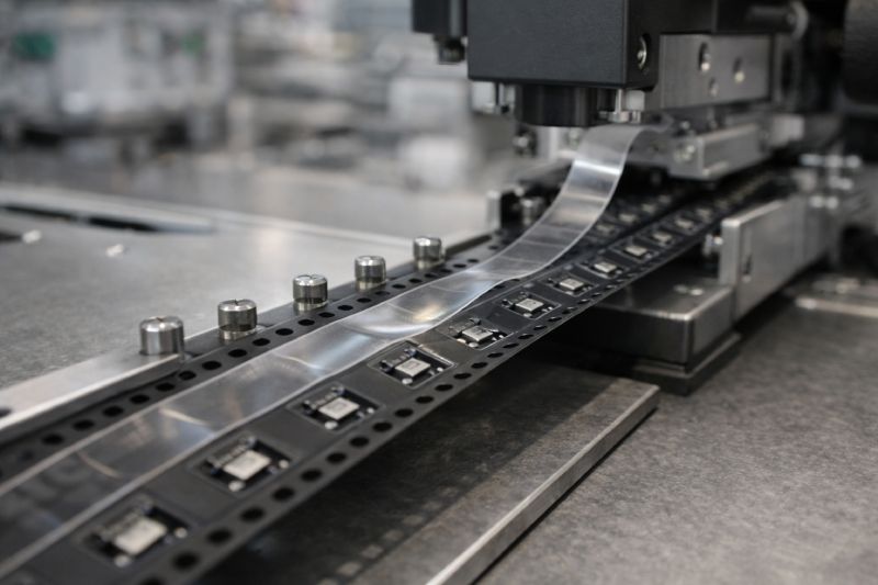
Real Feeder Validation
Feeder compatibility testing involves loading the carrier tape into a standard SMT feeder and running controlled indexing cycles. During this process, engineers observe:
-
Indexing smoothness
-
Sprocket hole engagement stability
-
Tape tracking alignment inside feeder rails
-
Peel synchronization with indexing
Even tapes that meet dimensional specifications can exhibit dynamic issues when subjected to continuous mechanical motion.
Dynamic Indexing Observation
Under real feeding conditions, several instability modes may appear:
-
Minor cumulative pitch drift becoming indexing offset
-
Micro-vibration during peel release
-
Pocket deformation under feeder tension
-
Inconsistent tape tension along the reel
Dynamic observation helps identify these risks before full-scale production.
Testing may include:
-
Low-speed validation cycles
-
Gradual speed increases to simulate production
-
Continuous long-length indexing to detect cumulative error
High-speed SMT environments are particularly sensitive to tolerance stack-up over extended feeding distances.
Component Jumping and Rotation Phenomena
One of the most common dynamic risks is component movement during peel or indexing.
Potential behaviors include:
-
Slight lateral shifting inside the pocket
-
Micro-rotation before pickup
-
Component bounce after sudden peel release
These effects may not be visible during static inspection but become apparent during real feeder simulation.
Such movement directly impacts:
-
Pick centering accuracy
-
Nozzle vacuum stability
-
Placement repeatability
If left undetected, these issues can reduce placement yield and increase machine compensation cycles.
Why Functional Testing Creates Competitive Advantage
Many carrier tape inspection methods focus only on dimensional compliance. However, feeder compatibility testing evaluates the tape as a mechanical interface within the SMT system.
It answers the real engineering question:
Will this tape remain stable under production speed and real machine conditions?
Functional feeding validation transforms carrier tape testing from specification verification into performance validation.
In high-precision SMT assembly—especially for miniaturized or high-value components—this step is not optional. It is essential for ensuring that static compliance translates into dynamic reliability.
Common Testing Mistakes in Carrier Tape Quality Control
Even when carrier tape testing is performed, gaps in methodology can create hidden risks. In high-speed SMT production, incomplete inspection is often more dangerous than no inspection—because it creates false confidence.
Below are some of the most common mistakes observed in carrier tape quality control programs.
Testing Only One Reel Instead of Batch Consistency
A single reel may meet dimensional and mechanical specifications, but batch-to-batch variation can still exist.
Common oversight:
-
Only first-article testing is performed
-
No sampling across production batches
-
No verification of cumulative pitch consistency between reels
Manufacturing process drift—especially in embossing temperature or tooling wear—can gradually affect pocket geometry or hole alignment.
Effective carrier tape testing should include:
-
Batch sampling
-
Periodic cumulative pitch verification
-
Process stability monitoring
Consistency across production lots is as important as compliance within one reel.
Ignoring Environmental Influence
Carrier tape materials respond to environmental conditions such as:
-
Temperature variation
-
Humidity fluctuation
-
Long-term storage conditions
Certain materials may become slightly more flexible under elevated temperatures or slightly brittle in low-humidity environments.
If dimensional testing is conducted only under controlled lab conditions, results may not reflect actual factory floor behavior.
Testing should consider:
-
Realistic production temperature ranges
-
Storage-to-production transition effects
-
Material recovery behavior after environmental exposure
Performing Only Dimensional Checks Without Functional Testing
This is one of the most common and critical mistakes.
Dimensional compliance does not confirm:
-
Feeding smoothness
-
Dynamic indexing stability
-
Peel synchronization
-
Component retention under vibration
Skipping functional feeding validation may allow dynamically unstable tapes to pass inspection.
Static compliance ≠ dynamic reliability.
Overlooking Cover Tape Interaction
Carrier tape and cover tape function as a system. Testing one without evaluating the other introduces risk.
Common oversight includes:
-
Measuring pocket geometry but ignoring peel behavior
-
Validating cover tape adhesion separately from feeder testing
-
Failing to assess peel consistency across reel length
Peel instability can compromise feeding performance even when carrier dimensions are perfectly controlled.
Why These Mistakes Matter
Carrier tape testing methods should be structured as a comprehensive system, not isolated checks.
Incomplete testing increases the risk of:
-
Placement yield fluctuation
-
Increased machine compensation
-
Unexpected feeder stoppage
-
Costly production interruptions
Robust SMT carrier tape testing integrates dimensional verification, mechanical evaluation, peel analysis, and functional feeding validation.
Quality control is not about checking boxes.
It is about systematically reducing production risk before the reel reaches the SMT line.
How to Evaluate Carrier Tape Testing Results
Carrier tape testing generates data—but data alone does not reduce risk. The key is interpreting test results according to the application context, SMT speed, component sensitivity, and production value.
Carrier tape inspection methods should support decision-making, not just documentation.
Below is a practical evaluation framework used in engineering environments.
Scenario 1 — Low-Speed SMT Production
If the project involves:
-
Moderate placement speed
-
Larger component sizes
-
Non-critical consumer electronics
Then minor dimensional variation may present lower operational risk.
In this case:
-
Basic dimensional verification
-
Standard peel consistency testing
-
Limited feeder simulation
may be sufficient.
However, cumulative pitch error should still be evaluated, even in low-speed lines.
Scenario 2 — High-Speed, High-Precision SMT
When production involves:
-
High indexing frequency
-
Fine-pitch components
-
Tight placement accuracy requirements
Testing standards must be significantly stricter.
Key evaluation priorities include:
-
Long-distance cumulative pitch measurement
-
Dynamic feeder simulation at target speed
-
Peel consistency under continuous indexing
-
Component movement observation
In high-speed environments, small deviations can escalate rapidly into placement misalignment.
Test results should be assessed not only against specification tolerances, but against machine compensation limits.
Scenario 3 — High-Value or Sensitive Components
If components are:
-
High-cost ICs
-
Precision sensors
-
Automotive or industrial-grade parts
The acceptable risk threshold becomes lower.
Even minor instability may justify enhanced testing procedures, including:
-
Extended functional feeding cycles
-
Batch-to-batch consistency validation
-
Environmental simulation before feeding
The higher the component value, the greater the justification for advanced carrier tape testing.
Decision Logic Summary
Carrier tape testing results should be evaluated using a risk-based logic:
-
Higher speed → stricter dimensional and dynamic validation
-
Higher precision → tighter cumulative tolerance control
-
Higher component value → broader testing scope
It is important to understand:
Passing specification limits does not automatically confirm suitability for every SMT scenario.
Effective evaluation connects test data to:
-
Production speed
-
Machine capability
-
Component sensitivity
-
Yield requirements
Carrier tape testing methods are not universal checklists.
They are adaptive risk control tools that must align with the technical demands of each project.
Testing Considerations for Custom Carrier Tape Projects
Custom carrier tape projects introduce additional variables that require structured testing before mass production. Unlike standard tape formats, custom designs may involve unique pocket geometries, non-standard component shapes, or specialized material selections. These factors increase uncertainty and make early-stage validation essential.
Testing During the Sampling Phase
During prototype development, carrier tape testing should focus on verifying:
-
Pocket fit accuracy for the specific component
-
Clearance balance between stability and easy pick access
-
Sprocket-to-pocket alignment consistency
-
Initial peel performance compatibility
Because custom tooling may still be undergoing adjustment, dimensional stability must be validated across multiple samples—not just one section.
Small deviations at the sampling stage often reveal tooling refinement needs before full production begins.
Importance of Small-Batch Functional Validation
Before approving mass production, small-batch validation runs are strongly recommended.
These tests should include:
-
Feeder compatibility testing under real indexing conditions
-
Continuous feeding simulation across extended length
-
Component stability observation during peel and pick
Short static inspections cannot capture dynamic risks. A short pilot reel run under production conditions provides far more reliable insight into real-world stability.
Material-Specific Testing Differences
Material selection significantly influences carrier tape behavior.
For example:
-
PS (Polystyrene) offers cost efficiency but may exhibit lower rigidity in certain thickness ranges.
-
PET (Polyethylene Terephthalate) provides improved toughness and temperature resistance.
-
PC (Polycarbonate) offers higher dimensional stability and impact resistance, often preferred in demanding applications.
Each material responds differently to:
-
Embossing precision
-
Environmental exposure
-
Mechanical tension during feeding
Therefore, custom carrier tape projects should adjust testing emphasis based on material selection. Higher-rigidity materials may prioritize cumulative pitch control, while more flexible materials may require enhanced deformation resistance evaluation.
Internal Engineering Alignment
For custom carrier tape development, testing should be treated as part of the design iteration cycle—not just final validation.
The process typically includes:
Design → Prototype → Dimensional verification → Functional feeding test → Tooling adjustment → Re-test → Approval
Skipping iterative testing in custom projects significantly increases downstream risk once production scales.
In summary, custom carrier tape testing must be more proactive than standard tape inspection. Early sampling validation, small-batch functional testing, and material-aware evaluation together ensure that a custom solution performs reliably under real SMT conditions.
Summary: Testing as Risk Control, Not Just Compliance
Carrier tape testing is fundamentally a risk control strategy, not merely a specification verification step. While dimensional accuracy, peel consistency, and mechanical integrity are measurable parameters, their true value lies in preventing instability before it reaches the SMT line.
In high-speed production environments, minor deviations can escalate into indexing errors, pick misalignment, and yield loss. Static compliance alone does not guarantee dynamic reliability.
Effective carrier tape testing integrates:
-
Dimensional verification
-
Mechanical performance evaluation
-
Peel force consistency analysis
-
Functional feeder simulation
Together, these methods ensure that carrier tape performs as a stable mechanical interface within automated assembly systems.
In modern SMT manufacturing, testing is not about passing inspection.
It is about eliminating uncertainty before production begins.



 Emial
Emial John Mr


