








Carrier Tape Inspection Machine Guide: Types, Parameters & SMT Stability Control
What Is a Carrier Tape Inspection Machine?
A carrier tape inspection machine is a precision measurement and vision-based system used to verify the dimensional accuracy, structural geometry, and consistency of embossed carrier tape before SMT assembly. It evaluates critical features such as pocket formation, pitch alignment, sprocket hole positioning, and overall tape stability to ensure reliable feeding performance in pick-and-place equipment.
In high-speed SMT production and high-density component packaging, even minor dimensional variations can disrupt feeder indexing and component positioning. Inspection systems are therefore not optional quality accessories — they are preventive stability tools designed to reduce feeding risk before reels reach the production line.
Modern inspection machines range from optical measurement stations to fully automated vision systems capable of real-time analysis and data logging.
In one sentence:
A carrier tape inspection machine verifies dimensional accuracy and structural consistency before SMT assembly.
Why Carrier Tape Inspection Is Critical in SMT
In SMT production, small dimensional deviations can quickly escalate into major process instability. A slight pocket width variation or pitch inconsistency may not appear significant during visual review, but under high-speed feeder indexing, these deviations directly affect component positioning accuracy.
The failure chain is predictable:
Dimensional deviation → Feeding instability → Placement shift → Yield loss
When pocket geometry is inconsistent, components may tilt, rotate, or shift during indexing. If pitch alignment drifts, feeder synchronization can become unstable. Sprocket hole misalignment affects indexing accuracy. These mechanical inconsistencies translate into pick errors, misplacement, tombstoning, or downstream inspection failures.
Carrier tape inspection is therefore not a symbolic quality checkpoint. It is a production stability safeguard. The goal is not merely to “confirm compliance,” but to prevent feeding-related variability before reels enter the SMT line.
In high-speed assembly environments where placement speeds exceed tens of thousands of components per hour, small geometric errors become amplified by motion dynamics. Inspection acts as a risk-control layer, protecting yield, uptime, and placement precision.
In practical terms, carrier tape inspection is a process control strategy — not a paperwork requirement.
What Parameters Do Carrier Tape Inspection Machines Check?
Carrier tape inspection machines are designed to evaluate the structural features that directly influence feeding stability and placement accuracy. Rather than checking cosmetic appearance, these systems focus on geometry, alignment, and repeatability — the mechanical foundations of SMT performance.
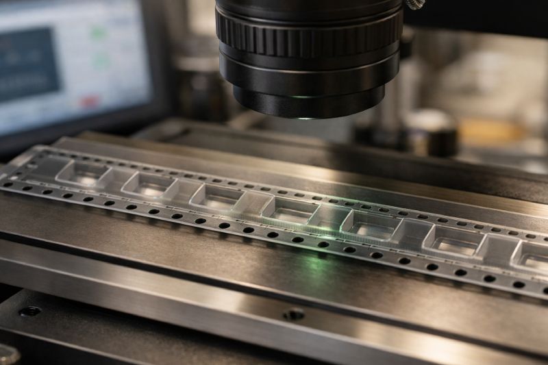
Below are the primary parameters typically verified.
Pocket Dimensions (Width, Depth, Geometry)
Pocket width, depth, corner radius, and bottom flatness determine how securely a component sits inside the cavity. If the pocket is too loose, components may rotate or shift during indexing. If too tight, insertion or release can become inconsistent.
Inspection systems analyze pocket uniformity across consecutive cavities, ensuring dimensional repeatability reel after reel. Geometry consistency is critical because feeding performance depends not on one pocket, but on thousands of identical pockets functioning predictably at high speed.
Pitch Consistency
Pitch refers to the center-to-center distance between pockets and sprocket holes. Even minor cumulative pitch drift can disturb feeder indexing synchronization.
Inspection machines measure pitch stability across multiple positions to detect progressive deviation. Consistent pitch ensures smooth mechanical engagement with feeder sprockets, reducing vibration, indexing stress, and component movement during transport.
Sprocket Hole Position & Alignment
Sprocket holes drive the entire feeding mechanism. Their position relative to pocket centers must remain stable and repeatable.
Misalignment can lead to uneven indexing, skewed tape tracking, or feeder wear over time. Vision-based inspection systems verify hole shape, spacing, and positional accuracy to ensure reliable engagement throughout the reel length.
Tape Width & Camber
Overall tape width affects how the tape sits within feeder rails. Camber (side-to-side curvature) influences straight-line travel stability.
Excessive camber can cause lateral wandering, increasing friction and reducing feeding consistency. Inspection systems evaluate edge straightness and width uniformity to prevent dynamic instability during high-speed indexing.
Cover Tape Seal & Peel Area (Selected Systems)
Some inspection platforms also assess cover tape sealing consistency and peel zone alignment. Irregular sealing can lead to uneven peel force during SMT operation.
By verifying seal positioning and structural uniformity, inspection machines help reduce the risk of sudden peel fluctuations that may disturb component stability during pick-up.
In essence, carrier tape inspection focuses on mechanical predictability. Every measured parameter contributes to one objective: ensuring that the tape behaves consistently under dynamic SMT conditions.
Types of Carrier Tape Inspection Machines
Carrier tape inspection systems vary significantly in capability, automation level, and application scenario. The right choice depends on production scale, quality sensitivity, and SMT speed requirements. Broadly, these systems fall into three categories.
Manual Optical Inspection Systems
Manual optical systems are typically used in sampling stages, prototyping, or small-batch validation. They rely on microscopes, measuring projectors, or calibrated optical tools to verify pocket geometry, pitch alignment, and hole positioning.
These systems offer flexibility and relatively low investment cost. They are ideal during new product development or custom carrier tape sampling, where engineering teams need controlled validation rather than high-speed throughput.
However, inspection speed depends on operator skill, and repeatability may vary. They are not suitable for large-volume production monitoring but remain valuable for engineering verification and troubleshooting.
Semi-Automatic Measurement Systems
Semi-automatic systems combine digital measurement platforms with partial automation. Tape sections are positioned into the machine, and software-assisted measurement tools capture key parameters such as pocket dimensions, pitch consistency, and hole alignment.
These systems improve repeatability compared to fully manual methods and support batch sampling inspection. Data recording features allow traceability and statistical analysis.
They are commonly used in medium-scale production environments where quality control is systematic but full inline automation is not required.
Fully Automated Vision Inspection Systems
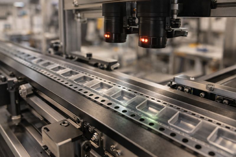
Fully automated vision systems represent the highest level of inspection capability. These machines use high-resolution cameras, motion control platforms, and real-time image processing algorithms to continuously scan carrier tape geometry.
They can operate inline with production equipment or as high-speed standalone inspection units. Automated systems detect dimensional deviations, alignment drift, and structural irregularities with consistent repeatability.
Key advantages include:
-
High inspection speed
-
Stable measurement accuracy
-
Real-time data logging
-
Statistical process control integration
These systems are ideal for high-volume manufacturing, high-speed SMT applications, and environments where yield sensitivity is critical.
Key Differences
| Factor | Manual | Semi-Automatic | Fully Automated |
|---|---|---|---|
| Precision Stability | Operator dependent | Digitally assisted | Highly consistent |
| Inspection Speed | Low | Moderate | High |
| Cost | Low | Medium | High |
| Best For | Sampling & R&D | Batch QC | Inline mass production |
Selecting the appropriate inspection type is not about choosing the most advanced system — it is about matching inspection capability to production risk level and operational scale.
Inline vs Offline Inspection Systems
Beyond automation level, carrier tape inspection machines are also categorized by how they integrate into the production workflow: inline or offline. This distinction affects response speed, risk control strategy, and overall investment planning.
Inline Inspection Systems
Inline inspection systems are installed directly within the carrier tape production or packaging line. As tape is formed and sealed, the inspection unit continuously scans dimensional parameters and structural features in real time.
The primary advantage of inline inspection is immediate feedback. If dimensional drift, pitch deviation, or alignment issues are detected, corrective action can be taken instantly. This minimizes material waste and prevents large volumes of non-conforming reels from progressing downstream.
Inline systems are ideal for:
-
High-volume production environments
-
Custom projects with tight dimensional tolerances
-
Operations prioritizing preventive quality control
However, inline integration requires higher initial investment and more complex system synchronization.
Offline Inspection Systems
Offline inspection systems operate independently from the production line. Tape samples or completed reels are inspected in a separate quality control area.
This approach provides flexibility and lower setup cost. It allows detailed measurement analysis without interfering with manufacturing throughput. Offline inspection is commonly used for batch verification, incoming material validation, or periodic quality audits.
Engineering Comparison
| Factor | Inline Inspection | Offline Inspection |
|---|---|---|
| Response Speed | Immediate | Delayed |
| Risk Containment | Preventive | Reactive |
| Investment Cost | Higher | Lower |
| Quality Strategy | Process-integrated | Sampling-based |
For high-speed SMT supply chains, inline inspection strengthens process stability. For smaller operations or moderate production volumes, offline systems may provide sufficient risk control.
Ultimately, the choice depends on how critical feeding stability is to overall yield performance and how much variability the production system can tolerate.
Accuracy & Resolution: What Level Is Really Needed?
Inspection accuracy should always be aligned with actual SMT operating conditions — not selected simply based on the highest available specification.
In high-speed SMT environments, dimensional sensitivity increases because dynamic forces amplify small geometric deviations. Faster indexing means that minor pitch drift or pocket inconsistency can translate into measurable placement variation. As SMT speed increases, inspection resolution must be sufficient to detect deviations before they influence feeder synchronization.
However, resolution requirements also depend on component size and packaging density. Smaller components with tighter seating tolerances demand finer measurement capability. Larger or more mechanically stable components may not require ultra-high inspection resolution.
A common engineering mistake is over-specifying inspection capability. Excessively high resolution increases system cost and data complexity without delivering proportional production benefit. If inspection sensitivity exceeds practical process variation limits, it may generate false alarms or unnecessary rejections.
The key principle is balance:
-
Match inspection resolution to component size and pocket geometry
-
Align measurement accuracy with feeder speed and placement precision
-
Avoid selecting equipment solely based on maximum technical specification
Effective inspection is not about achieving laboratory-grade precision — it is about ensuring production stability under real operating conditions.
Common Problems Carrier Tape Inspection Can Prevent
Carrier tape inspection is fundamentally a preventive strategy. By identifying structural deviations early, manufacturers can avoid a cascade of SMT performance issues that are often misattributed to feeder or machine instability.
Below are common problems that effective inspection systems help prevent.
Pocket Deviation
When pocket dimensions vary or geometry becomes inconsistent, components may not sit securely. During high-speed indexing, this can cause micro-rotation, tilting, or vertical instability. If undetected, these subtle shifts increase pick-up variation and placement offset, especially for small or lightweight components.
Pitch Drift
Progressive pitch inconsistency disrupts feeder synchronization. Even slight cumulative deviation affects indexing timing, which can lead to intermittent pick errors or inconsistent placement spacing across the PCB.
Without inspection, pitch drift may only be discovered after yield loss becomes visible in downstream AOI or functional testing.
D1 Misalignment (Sprocket Hole Offset)
Sprocket hole alignment drives mechanical indexing accuracy. If hole position shifts relative to pocket centers, feeder engagement becomes unstable. Over time, this can lead to tracking errors, feeder wear, and unpredictable feeding behavior.
Inspection systems detect this misalignment before reels enter SMT lines, preventing mechanical stress accumulation.
Camber Issues
Excessive tape curvature causes lateral wandering inside feeder rails. This increases friction and vibration, which directly affects component stability during indexing and pick-up.
If camber is not identified in advance, operators may incorrectly adjust feeder tension or machine parameters, masking the root cause.
Seal Inconsistency
Irregular cover tape sealing can produce uneven peel behavior. Sudden changes in peel dynamics may disturb component seating right before pick-up, especially in high-speed production.
By verifying seal consistency and peel zone alignment, inspection reduces the risk of dynamic instability during SMT operation.
When these issues are not detected early, the consequences extend beyond simple dimensional nonconformance. They can lead to:
-
Placement shift
-
Increased machine stoppage
-
Yield reduction
-
Troubleshooting time and production delays
Carrier tape inspection transforms these potential failures from reactive corrections into controlled, preventable risks.
How to Choose the Right Carrier Tape Inspection Machine
Selecting a carrier tape inspection machine should be based on production risk level, SMT speed, yield sensitivity, and batch volume — not simply on equipment sophistication. The objective is to match inspection capability with real operational needs.
Below is a practical engineering-based decision framework.
1. Consider SMT Speed
If your SMT lines operate at high indexing speeds and placement throughput is critical, automated or inline vision systems are generally recommended. Higher speeds amplify small dimensional deviations, so real-time monitoring or high-repeatability measurement becomes valuable.
For moderate-speed lines, semi-automatic systems may provide sufficient control through structured batch sampling.
2. Evaluate Yield Sensitivity
If your products involve high-density PCBs, fine-pitch components, or strict reliability requirements, higher inspection resolution and data logging capability are beneficial. In these scenarios, even minor feeding instability can significantly impact yield.
If yield tolerance is less sensitive and components are mechanically stable, a simpler inspection solution may be appropriate.
3. Analyze Batch Size & Production Scale
-
Small batch / custom projects → Manual or semi-automatic systems
-
Medium-scale production → Semi-automatic digital measurement
-
Large-scale continuous production → Fully automated or inline inspection
Inspection strategy should scale with production volume and risk exposure.
4. Define Quality Strategy
If your quality control philosophy is preventive and process-integrated, inline systems provide immediate feedback and reduce downstream correction costs.
If your approach is sampling-based validation, offline systems can offer structured quality verification at lower investment.
The most advanced system is not always the right system. Effective selection balances:
-
Required precision
-
Inspection speed
-
Budget constraints
-
Production risk profile
Ultimately, the right carrier tape inspection machine is the one that stabilizes your SMT process without creating unnecessary complexity.
Carrier Tape Inspection in Custom Projects
In custom carrier tape projects, dimensional verification becomes even more critical because pocket geometry is specifically engineered for a particular component. Unlike standard tape formats, custom designs often involve tailored cavity depth, optimized lateral clearance, and modified structural features to improve feeding stability.
Before mass production begins, inspection is used to validate that the manufactured tape matches the approved design intent. This typically includes prototype measurement, pocket geometry confirmation, pitch verification, and alignment checks. The objective is to confirm structural consistency before scaling to full-volume runs.
In custom programs, inspection serves three essential functions:
-
Verifying that tooling output matches design specifications
-
Ensuring feeder compatibility prior to SMT validation
-
Preventing large-scale production of dimensionally inconsistent reels
A structured sample validation process reduces risk at an early stage. Engineering teams commonly inspect pilot reels, conduct feeding simulations, and confirm dimensional repeatability before approving mass production.
For deeper reference, custom dimensional considerations are often addressed during the Custom Carrier Tape design phase and supported by structured analysis found in a Carrier Tape Design Guide.
In custom projects, inspection is not just quality control — it is design confirmation and risk prevention before full-scale deployment.
Integration with Tolerance & Specification Control
Carrier tape inspection is most effective when integrated with formal tolerance standards and documented specifications. Measurement alone has limited value unless it is evaluated against defined acceptance criteria and structural design intent.
Industry frameworks such as EIA-481 establish dimensional guidelines for carrier tape format, including pitch alignment, hole positioning, and pocket relationship to indexing features. Inspection systems verify that manufactured tape remains within these structured boundaries.
However, real-world production involves more than individual tolerances. It requires understanding tolerance stack-up — the cumulative effect of small dimensional variations across multiple features. Minor deviations in pocket center, pitch, and sprocket hole alignment may each fall within allowable range, yet together influence feeder stability.
Inspection data therefore supports:
-
Verification against formal specifications
-
Monitoring of process drift over time
-
Identification of cumulative deviation trends
-
Continuous process improvement
When inspection results are recorded and analyzed statistically, manufacturers can refine tooling, stabilize forming parameters, and reduce long-term variability.
For deeper engineering discussion, dimensional relationships are typically detailed in structured resources such as Carrier Tape Tolerance analysis and broader Carrier Tape Specifications documentation.
Integrated correctly, inspection is not a standalone activity — it is part of a controlled tolerance management system that protects SMT feeding stability.
Summary: Inspection as a Stability Strategy
Carrier tape inspection is not a formal checkpoint or a paperwork exercise. It is a structural stability strategy for high-speed SMT production.
Dimensional variation directly influences feeding consistency, and feeding consistency determines placement accuracy and yield performance. By verifying pocket geometry, pitch alignment, sprocket positioning, and structural integrity before reels reach the SMT line, inspection transforms potential variability into controlled risk.
The goal is not to pursue the highest possible measurement resolution, but to select the inspection system that aligns with your production speed, yield sensitivity, and operational scale.
In modern electronics manufacturing, stable feeding is not accidental — it is engineered. Carrier tape inspection is one of the key mechanisms that makes that stability predictable.



 Emial
Emial John Mr


