





Sprocket Hole Ovality: How to Inspect Carrier Tape Feeding Holes
Sprocket hole ovality is a carrier tape inspection concern that can affect feeding accuracy when a hole designed to be round becomes elongated, distorted, or damaged. However, not every oval-shaped feeding hole is defective. Some wider carrier tape designs intentionally use elongated holes along one edge.
To inspect carrier tape feeding holes correctly, engineers should first verify the approved hole design, then measure hole geometry, position, and pitch using suitable optical inspection equipment. Suspected defects should be evaluated against the approved drawing and, when necessary, checked through SMT feeder testing.
This guide explains how to distinguish intentional hole shapes from deformation, perform repeatable measurements, investigate possible causes, and document inspection results.
Is an Oval Sprocket Hole Always a Defect?
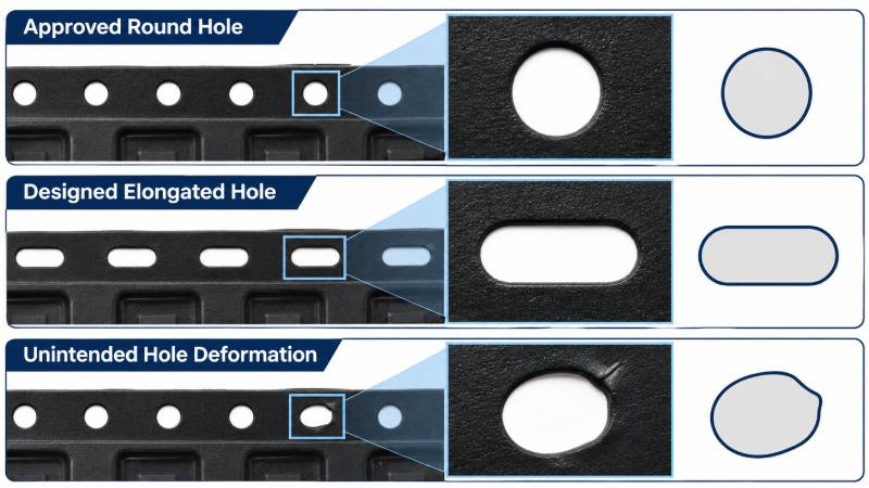
No. An oval or elongated sprocket hole is not automatically a manufacturing defect. The important distinction is whether its shape matches the approved carrier tape design.
Sprocket holes help the feeder advance the tape and maintain component positioning during automated assembly. Their geometry must work with the feeder mechanism, but different carrier tape configurations may use different hole designs.
Unintended Ovality in a Round Feeding Hole
Unintended sprocket hole ovality occurs when a hole specified as round develops an elongated or otherwise distorted profile.
Possible indications include:
-
A measurable difference between hole dimensions in different directions.
-
Local stretching around the hole boundary.
-
Asymmetric edges, burrs, cracks, or tearing.
-
Repeated deformation patterns along the feeding direction.
A hole can also appear irregular because of punching damage without forming a true ellipse. Engineers should inspect the actual boundary rather than relying on appearance alone.
Designed Elongated Sprocket Holes
Some wide embossed carrier tapes intentionally incorporate elongated sprocket holes.
For example, onsemi‘s Tape & Reel Packaging Standards documents configurations in which certain 32 mm, 44 mm, and 56 mm carrier tapes have round sprocket holes along one edge and oval holes along the opposite edge.
These designed elongated holes should not be judged using the same shape requirements as round driving holes.
The first inspection rule is to identify the specified hole type before evaluating ovality.
Hole shape, hole-center position, and hole pitch must also be evaluated separately. A round hole may be positioned incorrectly, while an elongated hole may be fully compliant with its approved drawing.
Which Sprocket Hole Dimensions Should Be Inspected?
A reliable sprocket hole inspection includes more than checking whether the opening looks round.
Engineers should evaluate hole geometry together with the dimensional features that control carrier tape indexing and pocket positioning.
Hole Diameter and Shape Measurements
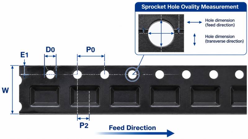
For a round sprocket hole, D0 identifies the nominal hole diameter in the applicable carrier tape dimensional specification.
Inspection should consider the hole boundary and the size measured in different directions.
Common measurements include:
-
Hole dimension parallel to the feeding direction.
-
Hole dimension perpendicular to the feeding direction.
-
Maximum and minimum measured hole dimensions.
-
Hole-center location.
-
Local edge damage, burrs, and distortion.
A directional size difference can help characterize elongation. However, ovality, roundness, and maximum-to-minimum diameter variation are not automatically interchangeable measurements.
If an inspection system calculates an ovality value, its calculation method must be defined. A simple difference between maximum and minimum dimensions may be useful for process monitoring, but it should not be presented as a universal EIA-481 acceptance formula.
Hole Pitch and Position
Several additional dimensions help determine whether a feeding problem is caused by hole shape or positioning.
| Dimension | Inspection purpose |
|---|---|
| D0 | Nominal round sprocket-hole diameter |
| P0 | Center-to-center spacing between consecutive sprocket holes |
| E1 | Position of the sprocket-hole center relative to the specified tape edge |
| P2 | Longitudinal relationship between sprocket-hole and pocket positioning |
| W | Overall carrier tape width |
The applicable drawing determines which measurements and tolerances must be verified.
For example, a feeder may index inconsistently because consecutive hole centers are incorrectly spaced, even when individual holes appear circular.
For a broader explanation of tape dimensions, see carrier tape dimensional measurement.
Why D0 and D1 Must Not Be Confused
D0 and D1 represent different features in conventional carrier tape drawings.
D0 identifies the round sprocket hole used in the feeding reference system. D1, where specified, identifies a hole associated with the pocket bottom rather than the primary feeding-hole diameter.
Confusing these dimensions can lead to incorrect inspection instructions or measurement reports.
Inspectors should therefore verify the dimension labels on the applicable drawing before selecting measurement points.
How to Measure Carrier Tape Sprocket Hole Ovality Step by Step
Sprocket hole ovality can be inspected using a measuring microscope or an optical vision system. The inspection should confirm the intended hole shape, measure its actual dimensions, and identify any deformation that could affect feeding performance.
Step 1: Check the Carrier Tape Drawing
Review the approved drawing to confirm whether the feeding holes should be round or intentionally elongated. Check the specified dimensions and inspection requirements before taking measurements.
Step 2: Prepare the Tape Sample
Place the carrier tape flat on a clean inspection surface without stretching or bending it. Record the tape width, material, lot number, and feeding direction.
If a feeding problem has occurred, examine both normal and suspected damaged holes.
Step 3: Inspect the Hole Shape
Use a calibrated optical measuring instrument to examine the hole edges. Adjust the lighting and focus to obtain a clear image.
Look for visible problems such as uneven edges, stretching, burrs, cracks, or localized deformation.
Step 4: Measure Hole Dimensions
For holes designed to be round, measure the opening in two directions:
-
Feeding direction: Parallel to the movement of the carrier tape.
-
Transverse direction: Perpendicular to the feeding direction.
Record both measurements and compare the hole profile with the approved design. For intentionally elongated holes, follow the dimensions specified in the drawing.
Step 5: Check Hole Pitch and Alignment
Measure the center-to-center spacing (P0) between adjacent sprocket holes. Check hole positioning relative to the tape edge and component pockets where required.
This helps distinguish hole deformation from spacing or alignment problems.
Step 6: Evaluate and Record the Results
Compare the measurements with the approved drawing and inspection criteria.
Record the measured dimensions, inspection images, and any visible defects. Repeat uncertain measurements before making an acceptance decision.
If the results are outside the approved requirements, the affected material should be reviewed according to the applicable quality-control procedure.
Important: A non-round hole is not automatically defective. Acceptance depends on the specified hole design and approved dimensional requirements.
How to Interpret Sprocket Hole Ovality Inspection Results
A measurement result becomes meaningful only when it is compared with the correct design requirement.
There is no reason to assume that one ovality limit applies to every carrier tape width, material, and hole configuration.
Compare Geometry with the Correct Drawing
For a round feeding hole, check the specified diameter, position, and any separately defined shape requirements.
For a designed elongated hole, inspect its specified dimensions and orientation instead of treating the long dimension as deformation.
Even when hole size is acceptable, an incorrect hole-center location or pitch may still affect feeding performance.
The applicable revision of EIA-481, customer documentation, and approved manufacturing drawings should be reviewed together. An internal inspection metric should not be described as a mandatory industry-standard tolerance unless the standard actually specifies it.
Distinguish Pass, Hold, and Reject Conditions
A practical inspection decision framework is shown below.
| Result | Evidence | Recommended action |
|---|---|---|
| Pass | Measurements satisfy the approved requirements | Continue according to the quality procedure |
| Hold | Measurement is uncertain, requirements are unclear, or an abnormal feature needs verification | Segregate or retain the sample for review |
| Reject | A nonconformity has been confirmed under the applicable acceptance procedure | Follow the approved nonconforming-material process |
The final decision must follow the customer‘s requirements and the responsible organization‘s quality procedures.
Check Measurement Repeatability
When results are close to an acceptance boundary, repeatability becomes particularly important.
Check the instrument calibration status, lighting, focusing, edge-detection settings, and sample positioning.
If different operators or measurement systems produce inconsistent results, the measurement method should be reviewed before the material is judged.
Depending on the inspection requirements, a formal measurement-system evaluation may be appropriate.
What Causes Unintended Sprocket Hole Ovality?
Unintended hole deformation can occur during manufacturing, subsequent handling, or actual feeder operation.
The observed shape should guide the investigation, but it should not be used as the sole basis for identifying the root cause.
Punching Tool Wear or Misalignment
Carrier tape punching operations depend on consistent tool alignment, material support, and controlled cutting conditions.
Potential contributors to hole-shape problems include:
-
Punch or die wear.
-
Misalignment between punching components.
-
Inappropriate tooling clearance.
-
Inconsistent material positioning.
-
Insufficient support during punching.
Tool wear or unstable punching conditions may also produce burrs and irregular hole edges.
When a similar defect appears repeatedly at the same position, engineers should review tooling condition, process records, and inspection samples from the affected production period.
Material Deformation During Processing
Carrier tapes may use materials such as PS, PET, PC, or ABS-based structures, depending on the packaging application.
Their response to cutting, forming, tension, and temperature can differ with the particular material grade, thickness, and processing conditions.
A hole may become distorted if the material is subjected to unsuitable mechanical stress during processing.
However, material selection alone does not establish whether a tape will develop oval sprocket holes. The actual material specification and manufacturing conditions must be evaluated together.
Winding, Handling, and Feeder-Induced Damage
Not every deformed hole originates at the punching station.
Possible contributors after punching include excessive web tension, poor tape guidance, mechanical pulling, or handling damage.
During SMT operation, abnormal engagement between the feeder sprocket and carrier tape may also damage hole edges.
Inspecting samples collected before and after feeder operation can help identify when the deformation developed.
| Possible cause | Evidence to investigate | Recommended check |
|---|---|---|
| Punch or die wear | Recurring irregular edges or burrs | Review tooling condition and production samples |
| Tool misalignment | Repeated asymmetric hole profiles | Check punch alignment and material support |
| Material deformation | Directional stretching or distortion | Review material and processing conditions |
| Winding or handling stress | Damage concentrated in affected tape sections | Inspect reel condition and web handling |
| Feeder interference | Damage appearing after feeding | Inspect sprocket engagement and feeder condition |
These are diagnostic possibilities rather than confirmed failure mechanisms for every case.
How Can Sprocket Hole Deformation Affect SMT Feeding?
Sprocket holes provide a mechanical reference for controlled carrier tape advancement.
When the driving-hole geometry is incorrect, engagement with the feeder mechanism may become inconsistent.
The effect depends on the actual hole profile, feeder design, tape stiffness, and other operating conditions.
Inconsistent Sprocket Engagement
A feeder sprocket must engage the appropriate tape holes while advancing the material.
If a round driving hole becomes stretched or damaged, the engagement clearance or contact location may change.
Depending on the mechanism, this can contribute to irregular advancement, localized mechanical stress, or reduced indexing repeatability.
An intentionally elongated hole should not be treated the same way because its function and allowable geometry are defined by the tape design.
Indexing Errors and Pick-Position Variation
During automated assembly, each component pocket should arrive at the intended pickup position.
Feeding instability may alter the location at which the component is presented to the pick-and-place nozzle.
Potential symptoms include intermittent indexing alarms, inconsistent pocket presentation, and pickup-position variation.
However, these symptoms are not unique to sprocket hole ovality.
Pocket pitch variation, carrier tape deformation, cover tape resistance, component movement, and feeder condition may produce similar effects.
When the Feeder Is the Actual Cause
A feeding problem may originate in the feeder rather than the carrier tape.
Inspect the sprocket mechanism, tape guides, loading path, and other relevant mechanical components.
If the same tape operates normally in another compatible and correctly maintained feeder, the original feeder warrants further investigation.
Similarly, damage that appears only after processing may indicate mechanical interference during feeding.
Static hole measurement should therefore be combined with controlled functional testing when the root cause remains unclear.
Troubleshooting Sprocket Hole Problems on an SMT Feeder
A structured troubleshooting sequence can prevent unnecessary tape replacement or tooling adjustments.
Start with the Reported Feeding Symptom
First, identify exactly what happened.
An indexing alarm, a visible jam, and a pickup-position error do not necessarily share the same cause.
Record the affected feeder, reel, lot, operating condition, and approximate tape position at which the problem occurred.
Inspect the suspected hole area for elongation, tearing, damaged edges, or changes in hole position.
Isolate Tape, Feeder, and Reel Variables
Use the following sequence when investigating suspected sprocket hole damage:
-
Stop the affected operation using the appropriate equipment procedure.
-
Preserve the questionable tape section and record the failure location.
-
Inspect the hole shape, adjacent hole pitch, and tape edge condition.
-
Compare the findings with the approved drawing.
-
Examine the feeder sprocket, guides, and tape path for abnormal contact or wear.
-
When permitted, compare performance using an approved reference tape or another compatible feeder.
-
Document whether the problem follows the tape, feeder, reel, or a particular operating condition.
Do not interchange sensitive production materials or modify feeder settings without following the applicable equipment and quality procedures.
Confirm the Root Cause Before Changing Tooling
If inspection reveals hole deformation, determine whether the same condition existed before feeder use.
Review available incoming, in-process, and final inspection records.
Repeated deformation in unused production samples may point toward a manufacturing process requiring investigation. Damage limited to used samples may indicate a downstream handling or feeding problem.
For related causes beyond the sprocket holes, refer to common SMT carrier tape feeding problems.
Corrective action should address the confirmed source of the problem, and its effectiveness should be verified through appropriate repeat measurements or feeder testing.
Inspection Records and Preventive Quality Controls
A useful inspection process must produce traceable evidence, not merely a pass-or-fail observation.
Recording hole measurements alongside manufacturing and feeder information helps engineers investigate recurring problems and distinguish separate failure mechanisms.
What to Record in an Inspection Report
The inspection record should identify the sample, the measurement method, and the basis for the acceptance decision.
| Inspection field | Information to record |
|---|---|
| Tape identification | Tape width, material, reel ID, and lot number |
| Drawing reference | Drawing number and approved revision |
| Sample information | Inspection stage, sample location, and feeding direction |
| Hole configuration | Round, elongated, or custom geometry |
| Shape measurements | Recorded directional dimensions or approved shape metric |
| Position measurements | Applicable D0, P0, E1, and other specified features |
| Measurement method | Equipment identification and inspection procedure |
| Supporting evidence | Image reference and visible edge conditions |
| Inspection decision | Pass, hold, reject, or engineering review |
| Follow-up | Investigation findings and corrective-action reference |
Acceptance limits, inspection frequency, and sampling quantities should come from the applicable quality plan.
Inspection Points Across Production Stages
Sprocket hole quality can be evaluated at different stages depending on process risks and customer requirements.
First-article inspection verifies the initial setup against the approved design.
In-process inspection can identify a developing dimensional or tooling issue before additional material is produced.
Final inspection verifies the specified product characteristics before release.
Incoming inspection at the assembly facility provides an opportunity to identify transportation or supplier-related concerns, while post-feeder examination helps investigate damage occurring during actual equipment operation.
Preventing Repeated Hole-Shape Defects
Preventive controls may include documented tooling inspection, stable material handling, defined dimensional measurement procedures, and traceability between production lots and inspection results.
When a recurring problem has been identified, engineering teams should review its confirmed cause and verify that the corrective action remains effective.
For new or modified carrier tape designs, sample approval and feeder compatibility evaluation may be required before production release.
The objective is to maintain consistent geometry while ensuring the tape works as intended in the customer‘s assembly process.
Frequently Asked Questions About Carrier Tape Feeding Holes
Can sprocket holes become deformed after carrier tape is loaded into an SMT feeder?
Yes. Mechanical interference, unsuitable engagement, or abnormal tension during feeding may damage sprocket hole edges. Engineers should compare samples collected before and after feeder operation and inspect the feeder mechanism. Hole deformation observed after use does not automatically prove that the original carrier tape was defective.
Is a slightly non-round hole automatically unacceptable?
No. Acceptance depends on the specified hole geometry, the approved drawing, and the applicable measurement and inspection criteria. An intentionally elongated hole may be correct by design. For a specified round hole, any suspected shape deviation should be measured using the approved method before a conformity decision is made.
Can a microscope image alone prove that a sprocket hole is out of tolerance?
Not necessarily. A microscope image may reveal elongation, burrs, or edge damage, but dimensional conformity requires an appropriate measurement scale, calibrated equipment, and a defined measurement method. Image quality, lighting, and edge selection can influence the result. A visual impression should not replace a traceable measurement.
Should engineers replace the carrier tape if only one feeder shows indexing problems?
Not immediately. A problem limited to one feeder may involve equipment wear, incorrect loading, or abnormal mechanical engagement. Engineers should inspect both the carrier tape and feeder, review the hole geometry against the drawing, and perform controlled comparisons where permitted. Material replacement should follow the investigation rather than precede it.
When to Request a Carrier Tape Engineering Review
An engineering review is appropriate when sprocket hole measurements fail to meet approved requirements, the drawing does not clearly define the inspected feature, or feeding problems continue after basic equipment and material checks.
To make the review more effective, prepare the following information:
-
Approved carrier tape drawing and revision.
-
Tape width, material specification, and hole configuration.
-
Clear images of the suspected sprocket holes.
-
Dimensional inspection results and measurement method.
-
Reel identification, production lot, and affected tape position.
-
SMT feeder model and observed failure symptoms.
-
Before-and-after feeding samples, when available.
These details help packaging and manufacturing engineers determine whether further dimensional inspection, tooling investigation, material evaluation, or feeder compatibility testing is necessary.
If the issue involves a custom tape specification, an updated drawing, or a new packaging application, Jiushuo can review the relevant requirements through its carrier tape products and associated engineering consultation process.
The most reliable approach is to confirm the intended hole geometry, measure the actual condition, and investigate the feeding system before deciding on corrective action.



 Emial
 John Mr