




Carrier Tape Pocket Wall Thinning: Measurement & Forming Checks
Carrier tape pocket wall thinning occurs when a plastic film stretches during pocket forming, leaving certain sidewalls, corners, or bottom areas thinner than the original material. Some thickness reduction is expected in thermoformed carrier tape. However, excessive or uneven thinning can increase the risk of pocket deformation, cracking, and unstable component support.
The correct approach is to measure the finished pocket at defined locations, compare the results with the original film thickness, and investigate the forming conditions responsible for localized thinning.
This guide explains how to measure embossed carrier tape wall thickness, interpret thickness distribution, troubleshoot forming-related problems, and verify corrective actions before mass production.
What Counts as Pocket Wall Thinning in Embossed Carrier Tape?
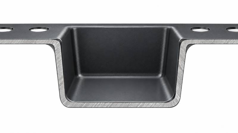
Embossed carrier tape is produced by forming three-dimensional component pockets from a flat thermoplastic film. As the material stretches into the required cavity shape, its thickness changes across different regions.
The pocket rim, upper sidewall, lower sidewall, bottom corner, and pocket floor may have different remaining thicknesses. This variation does not automatically indicate a manufacturing defect.
The engineering concern is whether the resulting thickness distribution provides adequate structural integrity for the component and packaging application.
Research published in the Journal of Thermal Engineering has examined how carrier tape tooling, forming conditions, and heat transfer affect pocket wall thickness distribution. The findings demonstrate why measurements from individual pocket locations are more informative than relying on starting film thickness alone.
Normal Material Stretching vs. Excessive Local Thinning
Normal thinning occurs as the film extends to form a pocket. The amount and location of material stretching depend on pocket geometry, material behavior, and forming conditions.
Excessive local thinning becomes a concern when a region has insufficient remaining material to meet the approved design or application requirements.
For example, a pocket may retain its intended outer dimensions while having a particularly thin corner. A dimensional inspection alone may not identify that condition.
Engineers should therefore distinguish between:
-
Uniform thinning: Relatively consistent material reduction across comparable areas.
-
Localized thinning: A significant reduction concentrated in a particular wall, corner, or transition.
-
Thickness variation: Differences in remaining thickness across locations or between successive pockets.
-
Structural failure: Cracking, tearing, permanent deformation, or another demonstrated loss of pocket integrity.
The objective is not necessarily to eliminate thickness variation, but to ensure the finished pocket meets its required performance.
Visible Signs That Require Further Inspection
Certain visual conditions may indicate that further measurement is necessary.
These include localized whitening, unusual translucency, distorted corners, inconsistent pocket shape, and cracks near the pocket base.
However, visual appearance is not a reliable thickness measurement. Color changes may result from material characteristics, surface texture, lighting, or stress-related effects.
A pocket that looks thinner should be checked using an appropriate measurement method rather than rejected solely on appearance.
Where Should Pocket Wall Thickness Be Measured?
Pocket wall thickness measurement should cover the regions where material stretching may differ, particularly the sidewalls and corner transitions.
Measuring only the flat carrier tape surface does not reveal the minimum remaining thickness inside a formed pocket.
A consistent measurement plan allows engineers to compare different samples, production lots, tooling conditions, and corrective-action trials.
Reference Thickness Before Forming
The first measurement is the original film thickness, identified as t₀.
This should represent the actual thickness of the material before pocket forming, preferably measured from the same incoming material lot.
The nominal film gauge listed on a material specification is useful for identification but should not automatically replace the measured reference thickness.
If unformed film is unavailable, an unaffected flat area may provide supporting information. However, its suitability as a reference must be verified because local processing conditions may have changed the material.
For troubleshooting, retain the material lot identification and the reference measurement method.
Critical Measurement Zones Around the Pocket
The following measurement plan provides a practical framework.
| Zone | Measurement Location | Inspection Purpose |
|---|---|---|
| Z0 | Unformed reference film | Establish starting film thickness |
| Z1 | Pocket opening or rim | Examine the transition into the cavity |
| Z2 | Upper pocket sidewall | Identify thinning near the cavity opening |
| Z3 | Lower pocket sidewall | Evaluate remaining wall thickness |
| Z4 | Bottom corner or radius | Locate concentrated thinning at the transition |
| Z5 | Pocket bottom | Evaluate the formed base thickness |
These zone labels are illustrative inspection references, not standardized EIA-481 measurement designations.
The actual measurement locations must be adapted to the approved pocket drawing. A pocket with an irregular cavity, stepped wall, or asymmetric component support feature may require additional measurement points.
Both longitudinal and transverse cross-sections may be necessary to identify the thinnest location.
Measurement Direction and Pocket Geometry
Pocket dimensions influence how the material is stretched.
The A0 and B0 dimensions describe the cavity opening geometry, while K0 relates to pocket depth. Together with wall angles, corner radii, and other design features, these dimensions affect the shape that must be formed from the original film.
A deeper cavity or a transition with a small radius may create localized stretching demands, depending on the forming method.
Engineers should record the section direction relative to the tape travel direction and the pocket orientation. Otherwise, measurements taken from different walls may be compared incorrectly.
For reference, the Microchip Product Tape and Reel Specification illustrates common embossed carrier tape dimensions and cavity designations.
These geometric references help define the inspection locations, but they do not replace direct pocket wall thickness measurements.
How to Measure Carrier Tape Pocket Wall Thickness
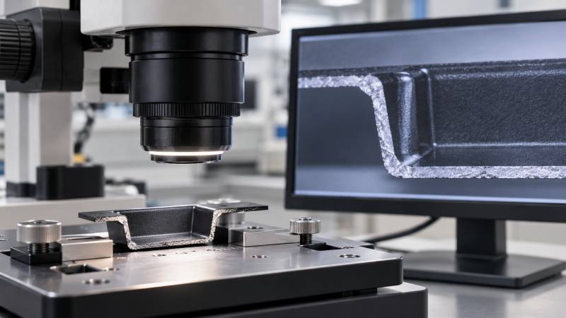
The thickness of a formed carrier tape pocket may differ from the original plastic film because the material stretches during forming. Checking different areas of the pocket helps identify uneven thickness.
Start by measuring the original film thickness as a reference. Then check the sidewalls, bottom corners, and base of the formed pocket using suitable measuring equipment.
For areas that are difficult to access, a prepared cross-section can make inspection easier.
Compare the measurements from several pockets to see whether the thickness is consistent. If noticeable differences appear repeatedly, review the pocket design, material properties, and forming conditions.
These checks help manufacturers monitor pocket quality and identify areas that may need further attention.
How to Interpret Pocket Wall Thickness Results
The minimum measured wall thickness, its location, and the overall thickness distribution should be evaluated together.
A useful analysis does not simply identify which pocket has the smallest numerical reading. It also examines whether the thin region is consistent, whether the condition has changed from approved samples, and whether it affects the intended application.
Minimum Thickness vs. Thickness Distribution
Minimum thickness identifies the thinnest measured region.
Thickness distribution describes how the material is distributed across the formed pocket.
Two pockets can have similar average wall thicknesses but different local thinning patterns.
For example, one pocket may have a comparatively even sidewall profile while another concentrates most of its thinning near a bottom corner.
The second pocket may require closer investigation even if its average thickness appears similar.
Engineers should review:
-
The location of the minimum measured thickness.
-
Differences between corresponding walls and corners.
-
Variation among successive pockets.
-
Changes relative to approved samples.
-
Whether the thin region coincides with deformation or cracking.
Measurement results become more meaningful when combined with pocket drawings and visual inspection.
When Is a Measured Thin Wall Acceptable?
There is no appropriate single acceptance percentage for every embossed carrier tape design.
A thin wall may be acceptable if the finished pocket satisfies the applicable material, dimensional, mechanical, and functional requirements.
The acceptance decision should consider the approved pocket drawing, customer specification, structural integrity, component retention, and relevant handling conditions.
Where feeder performance is important, dimensional and structural inspection may need to be supplemented by a functional trial.
A useful decision sequence is:
Measured wall thickness → Approved design requirements → Structural assessment → Functional verification → Acceptance or corrective action
If the acceptance criteria are missing or unclear, the proper action is to establish them through engineering review rather than inventing a limit after the measurement.
What Causes Uneven Pocket Wall Thinning During Forming?
Uneven pocket wall thinning may originate from material variation, heating conditions, tooling geometry, forming behavior, or thermal management.
These factors interact. A change that improves one region of a pocket may alter the thickness distribution elsewhere.
Troubleshooting should therefore begin with evidence from the actual production process.
Incoming Film Gauge and Material Variation
The starting film influences the amount of material available for forming.
Variation in the incoming film gauge may contribute to differences in the final pocket thickness.
Material formulation also matters. Different polymer grades may respond differently to heating, stretching, mold contact, and cooling.
When a wall-thinning problem appears after a material lot change, compare the incoming film specifications and actual measurements before changing the tooling.
For conductive or anti-static materials, any proposed material substitution should also preserve the required electrical and packaging properties.
Heating Uniformity and Film Temperature
Material temperature influences the way a thermoplastic film deforms during forming.
Uneven heating may lead to different stretching behavior across the pocket area.
However, temperature effects depend on the specific polymer, tool design, and forming method. Increasing or decreasing the temperature is not a universal correction.
Engineers should compare the actual film temperature, heating duration, heating uniformity, and relevant equipment settings.
A machine‘s temperature setpoint is not necessarily the temperature experienced by the film.
In a carrier tape thermoforming study, differences in tooling thermal behavior influenced the resulting pocket thickness distribution. The findings highlight the importance of evaluating actual process temperatures rather than relying only on nominal settings.
Pocket Depth, Corner Radius and Tooling Geometry
Pocket geometry determines how far and where the film must stretch.
K0 depth, sidewall angle, transition geometry, and corner radius can all influence local material distribution.
A sharp transition may create a concentrated deformation region. A deep pocket may require greater material extension than a shallow pocket made from the same starting film.
When localized thinning repeatedly appears at the same corner, review the corresponding tooling geometry.
Possible improvements may involve revising a radius, wall transition, or cavity feature, provided that the resulting pocket still meets component positioning requirements.
Tooling modifications must be evaluated against the full pocket design. Improving wall thickness should not introduce unacceptable component clearance, orientation, or release problems.
Forming Pressure, Vacuum and Timing
Depending on the equipment, pocket forming may involve positive air pressure, vacuum, mechanical assistance, or a combination of these methods.
The timing and magnitude of the applied forming forces influence how the heated film contacts the tooling.
If pressure application, tool movement, or forming duration is inconsistent, the final pocket geometry and thickness distribution may also vary.
Potential checks include pressure delivery, vacuum performance where applicable, timing synchronization, cavity venting, and mechanical movement.
These checks should match the actual forming equipment.
Reducing pressure is not automatically the right response to a thin wall. Inadequate forming force may produce incomplete pockets, while other conditions may concentrate material stretching in undesirable locations.
The correct adjustment must be determined through controlled trials.
Tool Temperature, Cooling and Surface Condition
Tooling affects both the shape of the pocket and the rate at which the formed film loses heat.
Differences in mold material, thermal conductivity, cooling behavior, and surface finish can influence the forming result.
Poor release behavior may also deform a pocket during tool withdrawal, creating a defect that could be mistaken for excessive stretching.
If pocket quality deteriorates during continuous production, investigate whether the tooling temperature or thermal conditions change as the process runs.
The Spartech Thermoforming Manual discusses material distribution, tool geometry, heating, and thinning problems in thermoplastic forming.
Its general principles can support troubleshooting, but corrective techniques intended for large thermoformed products should not be applied to carrier tape equipment without verification.
For a broader explanation of production stages, see the carrier tape manufacturing process.
Troubleshooting Pocket Wall Thinning by Defect Pattern
A wall-thinning pattern can help engineers decide which process records and equipment conditions to investigate first.
The pattern provides a starting point, not a confirmed root cause.
| Observed Condition | Initial Investigation | Recommended Verification |
|---|---|---|
| Repeated thinning at the same corner | Pocket geometry, tooling surface, forming sequence | Compare corresponding locations on multiple pockets |
| Thinning across several sidewalls | Film gauge, heating, material behavior | Review incoming film and forming records |
| Variation after a material lot change | Material thickness and formulation | Compare incoming material specifications and samples |
| Increasing variation during continuous production | Tool temperature and process stability | Compare start-up and steady-state measurements |
| Deformation during pocket release | Tool surface, cooling, release conditions | Inspect pocket shape before and after release where practical |
Thinning Repeatedly Appears at the Same Pocket Corner
A defect that consistently occurs at the same geometric location suggests that the local forming conditions deserve close attention.
Compare the affected corner with the approved pocket drawing and tooling geometry.
Review the local radius, wall angle, and contact conditions.
If multiple pockets exhibit the same thinning pattern, measure corresponding positions to establish whether the variation is systematic.
Thinning Appears Across Multiple Pocket Walls
When several walls are affected, investigate broader process conditions.
Compare the incoming film gauge, material lot, heating distribution, and forming settings.
If pocket dimensions also vary, evaluate whether the forming process is achieving the intended cavity shape consistently.
The evidence may indicate a material or process issue, but a specific cause should not be declared until the suspected factor has been tested.
Thinning Changes During Continuous Production
Some forming problems appear only after the equipment has been operating for a period of time.
Compare samples produced during start-up, stable operation, and the period when the abnormal condition appears.
Review the corresponding equipment records, especially actual tool temperature and any relevant process changes.
The objective is to determine whether the thickness variation follows a measurable process change.
Verify One Corrective Action at a Time
A controlled investigation should follow a repeatable sequence:
-
Identify the affected pockets and preserve representative samples.
-
Confirm the measurement method and defect location.
-
Review incoming material, tooling, and process records.
-
Select a plausible cause supported by the available evidence.
-
Make a controlled adjustment within approved operating limits.
-
Remeasure the same critical pocket locations.
-
Verify pocket dimensions and relevant functional performance.
-
Document the result and determine whether further action is necessary.
Changing several process variables simultaneously may make it difficult to identify which adjustment improved or worsened the result.
If an adjustment improves wall thickness but produces unacceptable pocket geometry, it should not be considered a successful corrective action.
How Pocket Wall Thinning Can Affect SMT Packaging Performance
Pocket wall thinning is primarily a forming and structural issue, but its consequences may extend into component packaging and automated handling.
The actual risk depends on the location and severity of the thinning, material properties, and the intended application.
Pocket Strength and Component Protection
An excessively thin pocket wall may be more vulnerable to local deformation or tearing under relevant handling loads.
If the pocket loses its intended shape, a component may no longer sit in the designed position.
This can become important for components with unusual geometry, concentrated contact points, or specific orientation requirements.
However, a thin region does not automatically mean that the pocket will fail. Structural and functional testing should establish whether the condition is unacceptable.
Cover Tape Sealing and Reel Winding
The pocket sidewall and the cover tape sealing land perform different functions.
A thin sidewall does not directly establish that the cover tape peel force is incorrect.
Nevertheless, significant pocket deformation may affect the flatness or stability of adjacent regions, depending on the design.
Potential downstream checks include sealing land condition, component clearance, pocket deformation during winding, and finished reel integrity.
Peel force must be evaluated independently using an appropriate method.
Feeder and Pick-and-Place Stability
During SMT operation, a carrier tape must move through the feeder while maintaining predictable component positioning.
If a pocket deforms enough to alter the component‘s position or release behavior, feeding and pick-and-place performance may be affected.
A pocket can meet its measured A0, B0, and K0 requirements while still having a localized structural weakness that warrants separate evaluation.
For this reason, wall thickness inspection should complement, rather than replace, dimensional and functional checks.
Forming Checks for First Article Approval and Mass Production
Corrective actions should be verified before being incorporated into routine production.
The required inspection plan depends on the product design, application risk, and approved quality requirements.
First Article Inspection After Tooling Setup
First article inspection should confirm that the formed pocket matches the approved engineering requirements.
Where wall thickness is identified as a critical characteristic, include defined thickness measurement locations in the inspection plan.
The first article record may contain the product drawing, material identification, incoming film thickness, pocket dimensions, local wall thickness results, and relevant forming setup information.
If the pocket has been redesigned to address thinning, compare the new measurements with the previously identified problem locations.
This helps confirm that the improvement has addressed the actual defect rather than shifting material reduction to another region.
Production Monitoring and Change Control
Once a forming process has been approved, production monitoring should focus on characteristics that can indicate changes in process stability.
The appropriate inspection frequency should be established through the product quality plan.
Material lot changes, tooling maintenance, equipment adjustments, and recurring defects may justify additional inspection.
A conventional optical inspection system may be useful for monitoring pocket geometry and visible defects. Direct wall thickness verification, however, requires a measurement method capable of assessing the relevant internal or exposed wall surfaces.
For additional information about inspection equipment, see the carrier tape inspection machine guide.
Sample Approval and Corrective Action Records
A structured record helps connect measurement results with engineering decisions.
| Record Field | Information to Capture |
|---|---|
| Product identification | Tape design and drawing revision |
| Material identification | Material grade and lot |
| Reference thickness | Measured incoming film thickness |
| Pocket dimensions | Applicable A0, B0, K0 and other controlled dimensions |
| Thickness results | Values at specified measurement locations |
| Minimum thickness | Lowest valid measured result |
| Measurement details | Instrument, method and inspection reference |
| Corrective action | Tooling or process change being evaluated |
| Verification result | Repeat measurements and relevant functional checks |
| Approval status | Decision against the applicable requirements |
This record structure can be adapted to the company‘s actual inspection and quality management procedures.
Additional carrier tape performance checks are discussed in the carrier tape testing methods guide.
Frequently Asked Questions About Pocket Wall Thinning
What affects carrier tape pocket wall thickness?
Pocket design, plastic material, and forming conditions can influence the thickness of different areas. The results may vary depending on the pocket shape and production process.
When should pocket wall thickness be checked?
Thickness can be checked during sample evaluation and routine quality inspection. Additional checks may be useful when materials, tooling, or forming conditions change.
What information is useful for reviewing pocket thickness?
A carrier tape drawing, material specifications, and clear product photos can help with an initial review. Available inspection records can provide further information about the finished pocket.
What to Prepare for an Engineering Review
If you notice uneven pocket wall thickness, prepare the carrier tape drawing, material information, and clear photos of the affected areas. Include any available thickness measurements and describe where the differences appear.
This information helps engineers review the pocket design, compare samples, and determine whether further inspection or adjustments to the forming process are needed.



 Emial
 John Mr