




Carrier Tape Curl vs Camber: Visual Checks and Root Causes
Carrier tape curl and camber are two different forms of deformation that can affect tape handling, dimensional inspection, and SMT feeder performance. Although both may appear as bending or distortion, they occur in different directions and require different inspection methods.
Camber refers to sideways curvature along the length of the carrier tape, while curl describes out-of-plane bending, such as tape rolling back after unwinding or its edges lifting upward.
Identifying the correct deformation is essential before investigating material properties, forming conditions, winding tension, or storage history.
This guide explains how to distinguish carrier tape curl from camber, perform practical visual and dimensional checks, identify possible root causes, and determine when further engineering evaluation is needed.
Curl vs Camber: What Does Each Carrier Tape Defect Look Like?
The most important difference between curl and camber is the direction of deformation.
Camber is primarily visible when looking at the carrier tape from above. Curl becomes apparent when examining the tape from the side or across its width.
Camber: Sideways Curvature Along the Tape Length
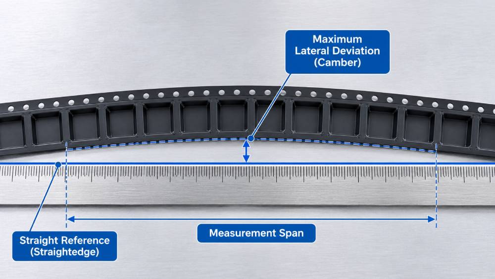
Carrier tape camber describes lateral deviation from a straight path within the nominal plane of the tape.
When a tape sample is placed alongside a straight reference, one edge may gradually move away from the reference line before returning toward it. The resulting shape resembles a shallow sideways bow.
Common observations include:
-
Gradual sideways bending along the tape length.
-
Inconsistent alignment with a straightedge.
-
Repeated lateral deviation over longer tape sections.
-
Sideways movement during unwinding or feeder operation.
Camber may be associated with uneven processing conditions, material stress, or tape guidance problems.
However, visible sideways movement during feeding does not automatically prove that the tape has excessive camber. Feeder alignment, sprocket-hole engagement, and reel positioning can produce similar symptoms.
Curl: Out-of-Plane Bending or Roll-Back
Carrier tape curl describes bending away from the tape‘s nominal plane. In this article, curl includes two practical inspection categories.
Longitudinal curl occurs when a tape bends along its length. A section removed from a reel may naturally curve back toward its wound shape instead of remaining relatively straight.
Transverse curl occurs across the tape width. One or both edges may lift, or the tape cross-section may develop a curved profile.
Possible observations include:
-
Tape ends curling upward after unwinding.
-
Persistent longitudinal curvature.
-
One edge lifting higher than the opposite edge.
-
Changes in tape shape after forming, sealing, or storage.
Some curvature is related to material flexibility and winding history. Its presence alone does not establish that the carrier tape is defective.
The condition must be evaluated against the applicable drawing, inspection method, and intended handling requirements.
Curl vs Camber vs Twist
Curl and camber should also be distinguished from twisting and localized edge deformation.
| Characteristic | Camber | Curl | Twist |
|---|---|---|---|
| Main deformation | Sideways deviation | Out-of-plane bending | Rotation along tape length |
| Best viewing direction | Top view | Side or end view | Multiple views |
| Typical appearance | Lateral bowing | Roll-back or edge lifting | Uneven rotation of the cross-section |
| Initial inspection | Straightedge alignment | Lift-off and profile observation | Cross-sectional orientation |
| Possible feeder concern | Lateral tracking | Tape seating | Irregular guide contact |
Edge waviness is another condition worth documenting. It involves localized irregularities along the tape edge rather than smooth, overall curvature.
Correct identification prevents engineers from investigating the wrong manufacturing process.
How to Visually Inspect Carrier Tape Curl and Camber
A reliable visual inspection begins with consistent sample handling.
Pulling the tape straight, pressing it flat, or applying excessive tension may temporarily conceal the deformation being investigated.
Prepare the Carrier Tape Sample
Before inspection, record the available identification details:
-
Carrier tape material and nominal width.
-
Tape thickness and pocket design reference.
-
Production lot and reel identification.
-
Sample position within the reel.
-
Winding direction and reel configuration.
-
Whether the tape is empty, component-loaded, or sealed.
Whenever possible, compare an affected sample with an approved reference sample of the same specification.
For intermittent problems, examine material from multiple reel positions rather than relying on a single short section.
Use a clean inspection surface and handle the tape carefully to avoid introducing additional bending or pocket damage.
Visual Check for Carrier Tape Camber
Place the sample in its natural condition beside a suitable straight reference.
Observe the tape from directly above, keeping the viewing direction perpendicular to the reference surface.
Check whether the tape edge remains approximately parallel to the straightedge or develops a noticeable sideways curve.
Pay attention to three characteristics:
-
Direction: Does the tape bow toward one side or change direction?
-
Distribution: Is the deviation gradual, localized, or repeated?
-
Consistency: Does the same pattern appear in other samples from the reel?
A camera positioned above the inspection surface can help document the observed shape.
Avoid stretching the tape or forcing it against the straightedge. The objective is to observe its condition before correction.
Visual Check for Longitudinal and Transverse Curl
For longitudinal curl, examine the tape from the side and observe whether the free section curves back toward its wound shape.
For transverse curl, examine the tape cross-section or edge profile using suitable support that does not flatten the feature being inspected.
Document:
-
Which section of the tape lifts or bends.
-
Whether both edges behave similarly.
-
Whether the deformation changes after a defined relaxation period.
-
Whether the pockets appear tilted or distorted.
-
Whether twisting is present at the same location.
When comparing multiple samples, use consistent handling, support, orientation, and observation conditions.
A photograph should include an appropriate reference scale where practical.
How to Measure Carrier Tape Camber and Document Curl
Carrier tape camber and curl require different inspection methods. Camber is measured as sideways deviation, while curl is evaluated by observing out-of-plane bending.
How to Measure Carrier Tape Camber
-
Place the carrier tape on a flat inspection surface without stretching it.
-
Position a straightedge alongside the tape.
-
Check the maximum sideways deviation within the specified measurement length.
-
Record the result and compare it with the applicable specification.
A 250 mm measurement span is commonly referenced in carrier tape technical specifications. However, acceptance limits must follow the approved drawing or customer requirements.
How to Check Carrier Tape Curl
Place the tape on a suitable inspection surface and observe its natural shape after unwinding.
-
Longitudinal curl: Check whether the tape bends upward or rolls back along its length.
-
Transverse curl: Check whether one or both tape edges lift above the reference surface.
Record the observed deformation and any measurements using a consistent inspection method.
Document Inspection Results
Record the tape width, material, lot number, measurement conditions, observed deformation, and inspection results. Include photographs when necessary.
Compare the findings with the applicable quality requirements before determining whether further engineering evaluation is needed.
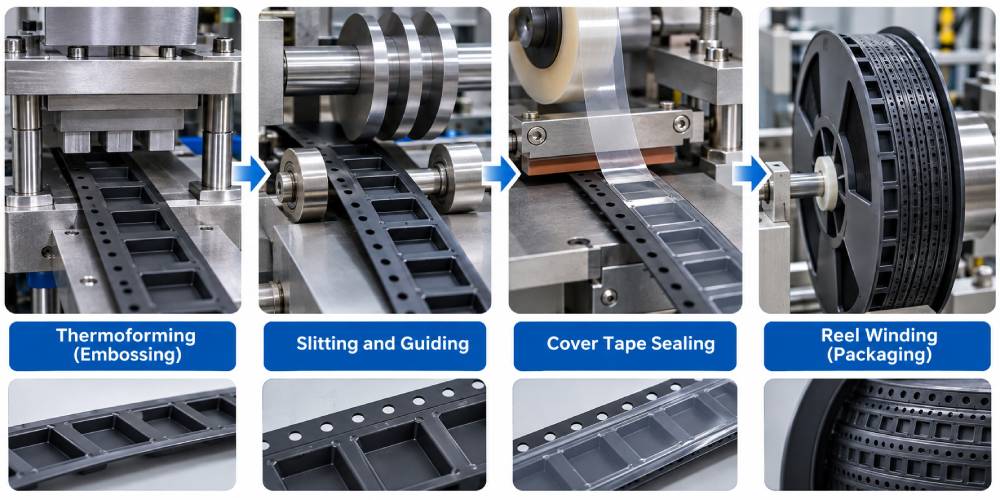
At Which Manufacturing Stage Did the Deformation Begin?
Before selecting a corrective action, engineers should determine when the tape first developed the observed shape.
A defect discovered during SMT feeding may have originated during raw material preparation, forming, slitting, sealing, winding, or storage.
Check Material Before and After Forming
Begin by examining the incoming material or unformed tape where samples are available.
Compare its condition with the material immediately after embossing.
If the curvature appears only after forming, investigate relevant heating, forming, cooling, and material-handling conditions.
Changes in pocket geometry, material thickness, or tooling setup may also need review.
Examine Slitting and Tape Guidance
If the deviation first appears after slitting or punching, inspect the associated web-handling process.
Potential investigation points include guide alignment, edge trimming, material tracking, and mechanical loading.
Repeated deformation at similar positions can indicate a process-related pattern.
However, the position alone does not establish the root cause.
Compare Sealing, Winding, and Storage Stages
Where applicable, compare samples before and after cover tape sealing.
Next, inspect the tape before winding, immediately after unwinding, and following storage.
These comparisons may help distinguish deformation introduced during processing from curvature associated with reel storage.
The key principle is to identify the earliest stage where the deformation can be demonstrated, rather than automatically blaming the last operation performed.
What Causes Carrier Tape Camber?
Carrier tape camber can result from several interacting mechanical and processing conditions.
The most useful investigation focuses on measurable changes rather than assuming a single cause.
Uneven Web Tension and Tape Tracking
During production, the carrier material passes through guides, rollers, and processing equipment.
Uneven loading or inconsistent guidance may influence the way the web travels through the machine.
Possible investigation points include:
-
Web tension consistency.
-
Roller and guide alignment.
-
Material tracking through processing stations.
-
Differences between equipment setups.
-
Changes after maintenance or adjustment.
If lateral curvature appears after a particular operation, engineers can compare samples before and after that station.
A process adjustment should be evaluated using the same inspection method to determine whether the change improved the condition.
Forming and Cooling Conditions
Embossed carrier tape undergoes deformation to create component pockets.
Heating, material stretching, forming pressure, and cooling can influence the resulting geometry.
Nonuniform processing may leave residual stresses that contribute to dimensional changes.
The effect depends on the actual material grade, tape thickness, pocket geometry, and production conditions.
For this reason, engineers should review process records and dimensional evidence before attributing camber to forming temperature or cooling alone.
Slitting, Winding, and Storage
Camber may also be associated with irregular material handling after forming.
Potential areas for investigation include uneven slitting conditions, winding alignment, and mechanical stress during reel preparation.
Storage conditions may influence material behavior, particularly when temperature and time affect dimensional stability.
Not every sideways curve originates during winding. Comparing samples from different process stages is necessary to determine whether winding introduced the deviation or merely made an earlier problem more noticeable.
What Causes Carrier Tape Curl?
Curl is influenced by the mechanical and thermal behavior of the tape material.
The pattern of deformation can help engineers identify which process conditions deserve investigation.
Winding Memory and Residual Stress
Carrier tape is commonly stored and transported in reels.
After unwinding, some materials may retain part of the curvature associated with the wound configuration.
The degree of shape recovery can depend on factors such as material stiffness, tape thickness, winding conditions, reel geometry, and storage duration.
For troubleshooting, compare samples from different reel positions under consistent conditions.
Check whether the observed curvature changes after the sample has been allowed to relax.
A temporary reduction in curl does not necessarily mean that the material will remain stable during further processing or feeding.
Thermal Forming and Uneven Cooling
During embossing, the carrier tape material is shaped into pockets.
If thermal or mechanical stresses are distributed unevenly, the material may develop a curved profile after cooling.
Potential contributing conditions include:
-
Nonuniform material heating.
-
Uneven deformation during pocket forming.
-
Cooling differences across the tape.
-
Local changes in material thickness.
-
Residual stress around formed pockets.
Different thermoplastic materials can respond differently to the same process conditions.
Polystyrene (PS), polycarbonate (PC), polyethylene terephthalate (PET), and ABS should therefore be evaluated according to their specific grades and processing requirements.
No single material should be described as universally resistant to curl.
Cover Tape Sealing Conditions
A change in tape profile after sealing may justify checking the sealing operation.
Potential factors include heat exposure, sealing pressure, material compatibility, and differential tension between the carrier tape and cover tape.
To investigate this possibility, compare matched samples before and after sealing.
Inspect whether the change occurs consistently along the sealed region and whether there is visible evidence of uneven processing.
Cover tape sealing should be considered a possible contributing factor only when the inspection supports that conclusion.
Material and Environmental Effects
The response of a carrier tape to its environment depends on its construction.
Paper-based carrier tapes may be sensitive to moisture-related dimensional changes, while embossed plastic tapes can respond to temperature, mechanical stress, and polymer-specific material behavior.
Excessive exposure to unsuitable conditions may affect dimensional stability.
The effect should be evaluated using the actual material specification and handling history rather than generalized assumptions.
For related inspection considerations, see quality control in paper carrier tape packaging.
How Do Curl and Camber Affect SMT Feeder Performance?
Carrier tape deformation becomes particularly important when it changes how the tape travels through an SMT feeder.
The feeder must guide, advance, and position the tape so that components are presented consistently for pick-and-place operations.
Camber and Lateral Tracking Problems
Excessive sideways curvature may cause the carrier tape to move toward a feeder guide or experience uneven contact during advancement.
Depending on the feeder design and tape configuration, possible symptoms include:
-
Lateral tape drift.
-
Increased guide friction.
-
Inconsistent tape tracking.
-
Intermittent indexing resistance.
-
Unstable component presentation.
These symptoms are not unique to camber.
Feeder guide wear, sprocket-hole positioning, reel alignment, and incorrect setup may produce similar behavior.
A camber measurement should therefore be considered together with equipment inspection.
Curl and Tape Seating Problems
Out-of-plane bending can affect how a carrier tape sits within the feeder path.
For example, persistent longitudinal curl may influence the tape‘s entry into the guide system.
Transverse edge lifting or twisting may create inconsistent contact with supporting surfaces.
The practical impact depends on the tape width, material stiffness, pocket geometry, and feeder construction.
A visible curl condition does not automatically mean a feeding failure will occur.
Functional testing is necessary when the specification or application requires it.
Separate Tape Deformation from Other Feeding Defects
Before concluding that curl or camber caused a feeding problem, check for other relevant conditions:
-
Sprocket-hole position or geometry defects.
-
Incorrect or inconsistent tape pitch.
-
Pocket deformation affecting component seating.
-
Inconsistent cover tape peeling.
-
Reel interference or abnormal unwinding resistance.
-
Feeder wear or setup problems.
The dimensions commonly designated W, P0, A0, B0, and K0 may be relevant during a broader inspection, depending on the observed symptom.
However, measuring these dimensions does not replace a direct camber or curl evaluation.
A controlled comparison using an approved reference tape can help determine whether the suspected deformation contributes to the feeding issue.
Troubleshooting Workflow and Corrective Action Decisions
A structured troubleshooting process helps prevent unnecessary process changes and repeated inspection.
The goal is to move from an observed symptom to a verified cause and a documented decision.
Step 1: Identify the Deformation
Begin by determining whether the issue is camber, longitudinal curl, transverse curl, twisting, or a combination.
Record where the condition was first noticed and preserve representative samples.
Do not straighten or rework the affected material before its original condition has been documented.
Step 2: Isolate the Suspected Process
Review available samples and records from different production stages.
Compare:
-
Incoming material and formed tape.
-
Material before and after slitting.
-
Sealed and unsealed samples.
-
Tape before winding and after unwinding.
-
Samples from different reel positions.
Focus on the point where the deformation first becomes observable.
Step 3: Verify the Root Cause
Select the suspected process condition and identify a corresponding verification method.
Where practical, change one relevant variable at a time and compare the result using the same inspection procedure.
A suspected cause should only be confirmed when the available evidence supports it.
The following matrix can help organize the investigation.
| Observed Condition | Possible Cause | Verification Check |
|---|---|---|
| Sideways curvature after slitting | Guide or slitting misalignment | Compare material before and after slitting |
| Camber after forming | Nonuniform processing or residual stress | Review forming and cooling conditions |
| Roll-back after unwinding | Winding memory or residual stress | Compare samples under defined relaxation conditions |
| Edge lifting after sealing | Sealing-related stress or material interaction | Compare sealed and unsealed samples |
| Sideways movement in feeder | Tape geometry or feeder guidance | Measure camber and inspect feeder setup |
| Twisting along tape length | Uneven deformation or handling stress | Inspect cross-sectional orientation at multiple positions |
The table identifies possible investigation paths, not confirmed causes.
Step 4: Determine Pass, Hold, or Reject
An inspection decision should be based on approved requirements and available evidence.
Pass: The material meets the applicable acceptance criteria and any required functional verification.
Hold: The inspection result is uncertain, the applicable acceptance criteria are not available, or the functional risk requires further evaluation.
Reject: A confirmed nonconformity exists under the applicable specification and quality-control procedure.
Material should not be released solely because the visible curvature appears minor.
Equally, a tape should not be rejected only because it looks curved when no relevant measurement or acceptance criterion has been established.
Step 5: Confirm Corrective Action Effectiveness
Once a corrective action has been implemented, repeat the relevant inspection under comparable conditions.
For a manufacturing-related issue, verify that the adjusted process produces acceptable material consistently.
For feeder-related problems, conduct an appropriate functional trial and document the results.
The final record should connect the original symptom, verified cause, corrective action, and supporting inspection evidence.
This approach provides a more reliable basis for process improvement than visual judgment alone.
Frequently Asked Questions About Carrier Tape Curl and Camber
Can carrier tape pass a camber inspection but still cause feeder problems?
Yes. Camber inspection evaluates lateral curvature, but feeder performance depends on several interacting factors.
A tape may satisfy its camber requirement while experiencing problems associated with sprocket-hole geometry, pitch variation, cover tape peeling, curl, or feeder alignment.
If feeding remains unstable, engineers should investigate the complete tape-and-feeder interaction rather than focusing on camber alone.
Does visible curling always mean the carrier tape must be rejected?
No. Visible curl does not automatically indicate a specification failure.
The evaluation depends on the approved drawing, inspection method, material behavior, and functional requirements.
A curved sample may still satisfy its applicable requirements, while another sample with a similar appearance may require further investigation because of its intended application.
Should curl be checked before or after cover tape sealing?
Checking both stages can be useful when investigating a change in tape profile.
A pre-sealing inspection establishes whether the deformation was already present. A post-sealing inspection helps determine whether a measurable change occurred during the sealing process.
The comparison should use representative samples and consistent measurement conditions.
Can rewinding permanently correct carrier tape curl?
Rewinding may change the visible shape of a tape, but it does not necessarily eliminate the residual stress or processing condition responsible for the original deformation.
Any improvement should be verified through repeated inspection.
Where feeder performance is a concern, functional validation may also be necessary before the material is approved for use.
What Information Should Be Prepared for an Engineering Review?
When carrier tape curl or camber is detected, providing clear product details and inspection records helps engineers identify the possible cause and determine the next steps.
Prepare the following information:
-
Tape specifications: Material, width, thickness, and pocket dimensions.
-
Sample details: Production lot, reel identification, and affected tape section.
-
Inspection results: Photos showing the deformation and available measurement records.
-
Processing history: When the deformation was first observed, such as after forming, sealing, or winding.
-
Feeder performance: Any feeding or alignment problems observed during SMT production.
If possible, provide both affected and normal tape samples for comparison.
These details help engineers evaluate the deformation, investigate potential causes, and recommend appropriate corrective actions.



 Emial
 John Mr