







Pocket-to-Sprocket Registration: Carrier Tape Inspection
Pocket-to-sprocket registration refers to the positional relationship between the component pockets and sprocket holes of a carrier tape. Accurate registration helps ensure that each pocket reaches its intended position when the tape advances through an SMT feeder.
Engineers typically check this relationship by measuring the longitudinal and transverse positions of pocket centers relative to designated sprocket-hole references. The P2 and F dimensions are particularly important for evaluating these relationships.
Even when pocket pitch and sprocket-hole dimensions meet their individual requirements, incorrect registration may still affect component presentation during automated assembly.
This guide explains how to measure pocket-to-sprocket registration, calculate positional deviations, identify possible manufacturing causes, and verify whether alignment problems affect SMT feeder performance.
What Does Pocket-to-Sprocket Registration Measure?
Pocket-to-sprocket registration describes how accurately a carrier tape pocket is positioned relative to the sprocket holes used for mechanical indexing.
During SMT assembly, the feeder advances the tape through a sprocket-driven or otherwise controlled indexing mechanism. The sprocket-hole pattern provides an important positional reference, while the pockets carry components toward the pickup location.
For reliable component presentation, these two features must maintain the intended geometric relationship.
Registration inspection focuses on two directions.
Longitudinal vs. Transverse Registration
Longitudinal registration describes the pocket‘s position along the tape feeding direction.
If a pocket is displaced forward or backward relative to its designated sprocket-hole reference, the component may arrive at a different longitudinal position than expected.
Transverse registration describes the pocket‘s position across the tape width.
A transverse offset changes the relationship between the pocket centerline and the sprocket-hole centerline. Depending on the feeder‘s guidance system, this may contribute to lateral pickup-position variation.
Both directions should be evaluated independently because they involve different geometric measurements and may have different causes.
Registration Error vs. Pitch Error
Registration error should not be confused with pitch error.
Pocket pitch describes the spacing between consecutive pockets. Sprocket-hole pitch describes the spacing between consecutive feeding holes.
Registration describes the relative position between these two patterns.
A carrier tape can have consistent pocket-to-pocket spacing and correctly spaced sprocket holes while the entire pocket pattern is shifted relative to the hole pattern.
Therefore, measuring pitch alone is not sufficient to confirm pocket-to-sprocket positional accuracy.
Which Dimensions Control Pocket-to-Sprocket Alignment?
Carrier tape engineering drawings use several dimensions to describe pocket geometry, hole positioning, and tape layout.
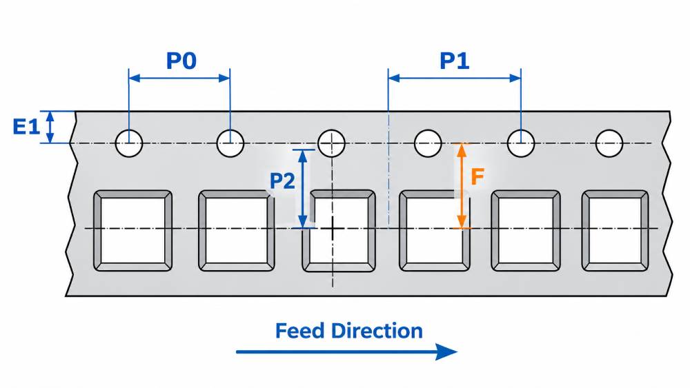
For registration inspection, P2 and F are the primary dimensions to evaluate. Other dimensions help establish the correct measurement references.
| Dimension | Description | Inspection Purpose |
|---|---|---|
| P2 | Longitudinal distance between a designated sprocket-hole center and pocket center | Checks pocket position along the feeding direction |
| F | Transverse distance between the sprocket-hole centerline and pocket centerline | Checks pocket position across the tape width |
| P0 | Sprocket-hole pitch | Verifies hole-to-hole spacing |
| P1 | Pocket pitch | Verifies pocket-to-pocket spacing |
| E1 | Sprocket-hole center position relative to the designated tape edge | Helps assess hole-row positioning |
| D0 | Sprocket-hole diameter | Checks feeding-hole geometry |
| W | Overall carrier tape width | Establishes tape format and dimensional context |
These dimensions should be interpreted using the approved carrier tape drawing and the applicable edition of EIA-481.
P2: Pocket Position Along the Feeding Direction
P2 defines a longitudinal relationship between a pocket center and a designated sprocket-hole center.
During measurement, the inspector identifies the correct reference hole and determines the distance between its center and the corresponding pocket center along the feeding direction.
Correct reference selection is important because pocket pitch may differ from sprocket-hole pitch.
For example, a carrier tape may have several sprocket holes associated with one pocket interval. Measuring from the wrong hole can produce an incorrect registration result even when the tape geometry itself is acceptable.
The inspection must follow the hole-to-pocket relationship shown on the approved drawing.
F: Pocket Position Across the Tape Width
F defines the transverse distance between the sprocket-hole centerline and the pocket centerline.
This measurement determines whether the pocket pattern is correctly positioned across the tape width.
An incorrect F dimension may indicate lateral displacement of the pocket pattern, an incorrectly positioned hole row, or another geometric alignment problem.
When investigating transverse registration, engineers should also check the sprocket-hole location relative to the tape edge.
Supporting Dimensions: P0, P1, E1, and D0
P0 and P1 help determine whether the hole and pocket patterns maintain their intended spacing.
E1 provides an additional reference for evaluating the hole row relative to the carrier tape edge.
D0 identifies the feeding-hole diameter and helps inspectors assess the geometry used to determine the hole center.
It is important to distinguish D0 from D1. In common embossed carrier tape drawings, D1 may identify a hole in the pocket area rather than the sprocket hole used for feeding.
A pocket-bottom hole should not automatically be treated as the pocket center or feeder indexing reference.
How to Prepare Carrier Tape for Registration Inspection
Accurate registration measurement begins with a stable inspection setup and clearly defined measurement references.
A measuring microscope, optical vision measuring system, or equivalent calibrated dimensional inspection equipment can be used, provided its capability is appropriate for the specified tolerance.
Before measuring, confirm the carrier tape drawing, orientation, material, and required inspection conditions.
Establish the Measurement Datums
Place a representative carrier tape section on a suitable inspection surface.
The tape should be adequately supported without excessive tension, stretching, or clamping pressure that could distort the embossed pockets.
Next, establish two measurement axes:
-
X-axis: Parallel to the carrier tape feeding direction.
-
Y-axis: Perpendicular to the feeding direction, across the tape width.
Identify the designated sprocket-hole row and the reference hole associated with the pocket being measured.
If the tape is slightly rotated in the camera image, align the measurement coordinate system with the actual tape reference before calculating offsets.
Otherwise, camera orientation can introduce apparent longitudinal or transverse errors.
Identify the True Pocket Center
The pocket center must be determined from the geometry specified on the approved drawing.
For a symmetrical rectangular pocket, the center may be obtained from the midpoints of its defined length and width boundaries.
However, some embossed pockets contain stepped walls, internal supports, asymmetric features, or nonrectangular cavities.
In those cases, the visible opening may not provide the correct measurement reference.
A0 and B0 describe pocket dimensions, but their measurement locations and the corresponding center definition must be interpreted according to the drawing.
Do not substitute the center of a pocket-bottom hole, internal feature, or loaded component unless the design explicitly defines that feature as the reference.
How to Measure Pocket-to-Sprocket Registration Step by Step
A repeatable inspection procedure is necessary to distinguish actual registration errors from measurement inconsistencies.
The following seven-step workflow can be adapted to the approved quality inspection procedure.
Step 1: Confirm the Approved Carrier Tape Drawing
Start by reviewing the drawing used for manufacturing and inspection.
Identify the carrier tape width, pocket geometry, P0, P1, P2, F, and relevant dimensional tolerances.
Confirm the feeding direction and the sprocket-hole reference used to define each pocket‘s position.
For wider carrier tapes or designs with multiple hole patterns, verify which row provides the applicable indexing reference.
Do not begin measurement using assumed nominal dimensions.
Step 2: Position the Carrier Tape for Measurement
Place the tape on the inspection fixture with its travel direction clearly identified.
Keep the inspection area stable and ensure that the pockets are not compressed or distorted.
If the tape exhibits curl or camber, use the approved support method rather than manually forcing the sample into a position that changes its geometry.
Adjust the inspection system so that the pocket boundaries and sprocket-hole edges can be identified consistently.
Step 3: Locate the Sprocket-Hole Centers
Capture a clear image of the designated reference holes.
Use the measuring system to identify each hole center based on its specified geometry.
For round sprocket holes, an appropriate circle-fitting or center-detection method may be used when the hole edges are suitable for that method.
If the hole is visibly deformed, damaged, or irregular, investigate the geometry before accepting the detected center.
A distorted hole boundary can introduce center-detection error and affect the registration result.
Record the measured hole-center coordinates in the established X-Y coordinate system.

Step 4: Locate the Pocket Centers
Next, identify the corresponding pocket centers.
Use the approved cavity reference geometry rather than estimating the center visually.
For a defined rectangular opening, the measurement system may determine the center from opposite boundary positions.
For irregular pocket shapes, use the drawing-defined reference features or an approved geometric construction.
Record the pocket-center coordinates using the same coordinate system as the sprocket-hole measurements.
This ensures that both features are compared using consistent references.
Step 5: Measure Longitudinal and Transverse Offsets
Once the hole and pocket centers are identified, calculate their relative positions.
For longitudinal registration, determine the X-direction distance between the selected sprocket-hole center and pocket center.
Compare this result with the specified P2 relationship.
For transverse registration, determine the Y-direction distance between the pocket center and the sprocket-hole reference line.
Compare this result with the nominal F dimension.
Use a consistent sign convention so that forward, backward, left, and right displacements can be distinguished.
Record the measured dimensions rather than reporting only a visual pass or fail.
Step 6: Repeat Measurements Across Multiple Pockets
A single measurement cannot establish positional consistency throughout a carrier tape reel.
Inspect multiple consecutive pockets according to the approved sampling plan.
Observe whether the measured registration error:
-
Remains approximately constant across the sample.
-
Changes periodically between pockets.
-
Gradually increases or decreases along the tape.
-
Appears only at isolated positions.
These patterns provide useful information for identifying potential manufacturing or inspection problems.
If a deviation is detected, additional samples from other reel positions or production stages may be needed.
Step 7: Record and Verify the Results
Document the nominal values, measured values, positional deviations, and applicable acceptance requirements.
Retain inspection images where appropriate.
If a reading appears inconsistent, repeat the measurement after checking feature detection, sample positioning, and equipment setup.
Compare confirmed results with the approved dimensional requirements before classifying the sample as acceptable or nonconforming.
Any unresolved deviation should be reviewed using the applicable quality procedure.
How to Calculate and Interpret Positional Registration Error
Registration error is the difference between the measured pocket position and its intended position relative to the selected sprocket-hole reference.
The measurement should use a consistent coordinate system so that the direction of the deviation remains meaningful.
Calculate Longitudinal Registration Error
For a drawing that defines the longitudinal relationship using P2, the deviation can be calculated as:
ΔX = P2(measured) − P2(nominal)
Where:
-
ΔX: Longitudinal registration deviation.
-
P2(measured): Actual measured longitudinal relationship.
-
P2(nominal): Intended longitudinal relationship from the drawing.
A positive result indicates displacement in the defined positive measurement direction. A negative result indicates displacement in the opposite direction.
This interpretation requires the inspector to use the same directional reference for the nominal and measured values.
Calculate Transverse Registration Error
The transverse deviation can be expressed as:
ΔY = F(measured) − F(nominal)
Where:
-
ΔY: Transverse registration deviation.
-
F(measured): Actual measured transverse relationship.
-
F(nominal): Intended transverse relationship from the drawing.
The sign indicates the direction of displacement within the defined coordinate system.
If the measured F dimension is incorrect, verify whether the deviation comes from the pocket position, hole-row position, or an incorrectly established measurement datum.
Compare Results with Approved Limits
A positional deviation is not automatically a dimensional failure.
The result must be compared with the applicable tolerance specified by the approved drawing, customer requirement, or relevant standard.
For example, an inspection record can use the following structure:
| Measurement | Nominal Value | Measured Value | Deviation | Specified Limit | Result |
|---|---|---|---|---|---|
| Longitudinal registration (P2) | Drawing value | Actual reading | ΔX | Drawing requirement | Pass / Fail |
| Transverse registration (F) | Drawing value | Actual reading | ΔY | Drawing requirement | Pass / Fail |
If the drawing specifies a geometric position tolerance, the inspection must follow its defined datums and tolerance zone rather than relying only on separate X and Y comparisons.
Measurement repeatability and uncertainty should also be considered when results approach an acceptance limit.
The objective is to determine whether the manufactured pocket pattern meets its approved geometric requirements, not to assume that every measurable deviation is unacceptable.
What Causes Pocket-to-Sprocket Misregistration?
Pocket-to-sprocket misregistration can be associated with manufacturing alignment, web positioning, material behavior, or measurement problems.
The observed deviation pattern can help engineers prioritize the investigation, but it should not be treated as proof of a specific root cause.
Forming and Punching Tool Alignment
Carrier tape manufacturing requires the pocket-forming process and sprocket-hole pattern to maintain their intended relative positions.
Depending on the manufacturing process, incorrect tooling alignment or synchronization may shift the pocket pattern relative to the feeding holes.
A repeatable registration offset may justify reviewing tooling setup, positioning references, and adjustments made during maintenance or changeover.
Comparing current samples with approved reference samples can help identify when the deviation first appeared.
Indexing and Web Positioning Variation
The carrier tape material must advance through manufacturing equipment in a controlled manner.
Variation in web movement, guiding, feed advancement, or process synchronization may affect the relative positions of pockets and sprocket holes.
If the registration deviation changes repeatedly or periodically along the tape, engineers should review the relevant positioning mechanisms and machine records.
It is also important to determine whether the variation affects pocket spacing, hole spacing, or the relationship between the two patterns.
Material Movement and Dimensional Instability
Material behavior can influence dimensional stability during forming, cooling, handling, and storage.
Carrier tapes may be manufactured from PS, PET, PC, ABS, or other materials selected for specific packaging requirements.
Their forming behavior can differ depending on material grade, thickness, processing temperature, mechanical tension, and tool design.
If registration variation appears after a process or material change, engineers should review the relevant forming conditions and material specifications.
Material selection alone does not establish the cause of a positioning defect.
Recognizing Registration Error Patterns
| Observed Pattern | Possible Contributors | Recommended Verification |
|---|---|---|
| Consistent longitudinal offset | Tooling setup or process positioning offset | Compare approved drawing, tooling references, and initial samples |
| Consistent transverse offset | Lateral tooling alignment, hole-row position, or web guidance | Check F, E1, and relevant reference features |
| Periodic registration variation | Repeating mechanical or indexing variation | Compare deviation pattern with equipment operating cycles |
| Progressive position change | Web movement, dimensional variation, or reference instability | Measure a longer sample and review process records |
| Isolated abnormal reading | Local damage, feature deformation, or measurement error | Reinspect the affected area and adjacent pockets |
A useful diagnostic principle is to compare how pocket centers and sprocket-hole centers change together.
If both patterns shift similarly relative to the tape edge, the issue may differ from a situation where only the pocket pattern moves relative to an otherwise stable hole row.
How to Verify Whether Misregistration Affects SMT Feeder Performance
Static registration measurement confirms the geometric relationship between carrier tape features.
However, a dimensional inspection alone cannot fully predict component pickup behavior inside an operating SMT feeder.
The feeder mechanism, tape guidance, component clearance, and machine settings also affect the position at which components are presented.
Compare Static Measurements with Feeder Observations
If a carrier tape shows a measurable registration deviation, a controlled feeder test can help determine whether the deviation contributes to pickup-position problems.
Where practical, compare a known reference tape with the suspected tape using the same suitable feeder configuration.
Observe the pocket presentation position after indexing.
Check whether the displacement is repeatable and whether its direction corresponds to the registration deviation measured during static inspection.
The component‘s actual position inside the pocket should also be considered. A component may move or rotate within an accurately positioned pocket if its clearance or retention conditions allow it.
Therefore, pocket-center accuracy and component-center presentation should be evaluated as related but separate issues.
Rule Out Equipment-Related Causes
Before attributing a pickup error to the carrier tape, verify the relevant feeder conditions.
Check that the feeder is configured for the correct tape format and pocket pitch.
Inspect the indexing mechanism and tape guidance for abnormal engagement, wear, or mechanical interference.
If pickup instability occurs during cover tape removal, evaluate whether peeling behavior or component movement is contributing to the problem.
For a broader diagnostic procedure, see Carrier Tape Feeding Problems: Causes, Symptoms & Engineering Solutions.
Registration measurements become most useful when they are compared with controlled observations of actual feeder performance.
What Should a Pocket Registration Inspection Report Include?
A registration inspection report should make the measurement results traceable and allow another engineer to understand how the values were obtained.
The report should identify the inspected carrier tape, measurement references, equipment, and applicable requirements.
Required Inspection Records
A practical report should include:
-
Sample identification: Carrier tape type, lot number, reel identification, and sample location.
-
Drawing information: Drawing number, revision, material, and relevant dimensional specifications.
-
Measurement setup: Equipment identification, calibration status, feeding direction, and reference datums.
-
Measured dimensions: P2, F, and any supporting dimensions required by the inspection plan.
-
Calculated deviations: Longitudinal and transverse offsets from nominal positions.
-
Inspection evidence: Measurement images, recorded observations, and relevant measurement conditions.
-
Acceptance decision: Comparison with approved requirements and the resulting inspection status.
The report should distinguish actual readings from nominal values and tolerance limits.
Sample Approval and Production Monitoring
For a new carrier tape design, initial inspection can help verify whether the manufactured pocket and hole patterns match the approved drawing.
After tooling adjustments, material changes, or other significant process modifications, additional measurements may be appropriate to confirm positional consistency.
Production inspection results can also be compared with approved reference samples to identify changes in registration behavior.
The required sampling frequency and acceptance procedure should follow the manufacturer‘s documented quality plan and any applicable customer requirements.
For additional background on dimensional measurement, refer to How to Measure Carrier Tape Dimensions Correctly for SMT.
Frequently Asked Questions About Pocket-to-Sprocket Registration
Can pocket-to-sprocket registration be incorrect when P0 and P1 are within tolerance?
Yes. P0 and P1 describe hole and pocket spacing, while registration describes their relative positions. Both patterns may have acceptable pitch values but still be offset from each other. P2 and F should be checked independently against the approved drawing.
Can a pocket-bottom hole be used as the pocket-center reference?
Not automatically. A pocket-bottom hole may have its own dimensional and positional requirements. The pocket center should be determined using the approved cavity geometry. An internal hole or feature should only serve as a registration reference when the drawing explicitly permits it.
Is optical inspection necessary for every carrier tape design?
Not necessarily. The inspection method depends on the required tolerance, geometry, and approved procedure. Optical equipment is useful for locating hole and pocket centers without mechanical contact, but any suitable calibrated measurement system may be used if it provides the required capability.
Can pocket registration be measured after cover tape sealing?
It depends on the inspection method and visibility of the required features. Sprocket holes usually remain accessible, but cover tape and packaged components may obstruct pocket-center measurement. Direct cavity inspection is generally easier before sealing unless an approved method can measure the relevant geometry afterward.
When Should You Request a Carrier Tape Registration Review?
If pocket-to-sprocket registration measurements fall outside approved requirements or repeated SMT pickup-position problems remain unresolved, a more detailed engineering review may be appropriate.
Before requesting a review, prepare the carrier tape drawing, relevant P2 and F measurements, inspection images, sample identification, and a description of the observed feeding problem.
Information about tape material, pocket dimensions, and any recent tooling or process changes can also support the investigation.
Where the issue involves pocket geometry or tooling design, a review of the existing embossed and custom carrier tape requirements may help determine whether adjustments or additional sample validation are needed.
The goal is to confirm the actual source of positional variation and establish a measurable basis for corrective action before production continues.



 Emial
 John Mr