

Carrier Tape First-Piece Inspection: Shift-Start Checklist
Carrier tape first-piece inspection is a quality control procedure used to verify that a production line is correctly set up before continuous manufacturing begins. At the start of a shift or after a significant process change, operators inspect a representative sample to confirm that pocket dimensions, sprocket holes, tape alignment, and forming quality meet approved specifications.
A reliable shift-start inspection should cover machine setup, material identification, dimensional measurements, visible defects, and production release approval. The purpose is to detect setup errors before they affect a larger quantity of carrier tape.
This guide provides a practical first-piece inspection checklist for embossed carrier tape production, including measurement priorities, common problems, and corrective actions.
When Should a Carrier Tape First-Piece Inspection Be Performed?
First-piece inspection verifies the condition of a production process at a specific point in time. It is particularly important when machine settings, tooling, materials, or operating conditions may have changed.
Unlike routine inspection of finished products, first-piece checks focus on whether the current setup is ready for continued production.
Shift-Start and Process-Change Triggers
Common situations that may require first-piece verification include:
-
Beginning of a production shift: Confirm that the current setup produces acceptable carrier tape before continuing the planned run.
-
New production order: Verify that the machine configuration matches the new product drawing.
-
Tooling replacement: Check pocket geometry and sprocket-hole alignment after a forming or punching tool is changed.
-
Material change: Confirm the correct material grade and evaluate any characteristics affected by the change.
-
Machine adjustment: Reinspect relevant features after changes to forming conditions, indexing, or web tension.
-
Maintenance or abnormal stoppage: Verify affected characteristics before restarting continuous production.
The exact inspection triggers should follow the approved production control plan. A shift handover without equipment adjustment may require a different verification procedure from a complete product changeover.
First-Piece Inspection vs. First Article Inspection
First-piece inspection, first article inspection, and in-process inspection serve different purposes.
| Inspection type | Primary purpose | Typical timing |
|---|---|---|
| First-Piece Inspection | Verify the current machine setup and representative output | Shift start, setup, or relevant process change |
| First Article Inspection (FAI) | Perform broader verification of a new or significantly changed product or process | Initial production or major changes |
| In-Process Inspection | Monitor production consistency and detect variation | At defined intervals during production |
A successful first-piece inspection confirms that the inspected sample meets the applicable release criteria. It does not guarantee that every subsequent pocket will remain within specification.
Continued process monitoring is still necessary.
Pre-Start Setup Checks Before Taking the First Sample
A first-piece inspection should begin with verification of the production setup.
Even when the first formed pockets appear acceptable, production should not be released if the wrong material, tooling, drawing, or machine recipe has been selected.
Confirm the Production Order and Approved References
Before collecting a sample, the operator should verify the following information against the current work order:
-
Carrier tape part number and product identification.
-
Approved engineering drawing and revision.
-
Tape width and specified pocket dimensions.
-
Required pocket pitch and sprocket-hole geometry.
-
Material type, grade, and relevant ESD requirements.
-
Material batch or lot number.
-
Customer-specific inspection requirements.
-
Approved reference sample, if applicable.
Material identification is particularly important when switching between PS, PET, PC, ABS, or specially formulated conductive and static-dissipative materials.
Different materials can behave differently during forming. However, a material change does not automatically require every possible material-property test at shift start. The control plan should identify which properties require verification.
Verify Tooling, Machine Settings, and Measuring Equipment
The next step is to confirm that the machine is prepared to produce the specified carrier tape.
Check that the correct forming tool is installed and that no visible damage or abnormal wear is present.
The applicable setup checks may include:
-
Forming temperature and heating conditions.
-
Forming pressure or vacuum settings.
-
Forming cycle timing.
-
Film feeding and indexing settings.
-
Punching-tool alignment.
-
Web tension and guide positioning.
-
Material tracking through the machine.
-
Machine recipe identification.
These parameters should be compared with the approved process settings rather than adjusted according to generalized values.
Measuring instruments must also be suitable for the required inspection. Optical measuring systems, depth gauges, microscopes, or dedicated carrier tape inspection equipment should be checked for the required calibration or verification status.
Only after the setup is confirmed should a representative first-piece sample be collected.
Shift-Start Carrier Tape First-Piece Inspection Checklist
The following checklist provides a structured reference for inspecting embossed carrier tape before production release.
It is intended as an engineering checklist framework. The actual inspection items, sample quantities, acceptance limits, and approval requirements must be defined by the applicable drawing and production control plan.
Collect and Identify the First-Piece Sample
The sample should represent material produced under the intended operating conditions.
If the machine requires an approved stabilization or trial period, material produced during that period should be identified separately from the sample used for release inspection.
Record the production order, machine identification, material lot, and sampling time so the inspection results can be traced to the correct setup.
The sample length and number of pockets inspected should follow the documented sampling procedure.
First-Piece Inspection Checklist
| Inspection item | What to verify | Recommended method |
|---|---|---|
| Product identification | Part number and drawing revision match the order | Document verification |
| Material identification | Correct material grade and batch | Material record check |
| Carrier tape width (W) | Width matches the approved specification | Calibrated dimensional measurement |
| Pocket dimensions (A0/B0/K0) | Pocket geometry meets drawing requirements | Optical or dimensional measurement |
| Pocket pitch (P1) | Pocket spacing is consistent | Optical measurement |
| Sprocket-hole pitch (P0) | Hole spacing meets specification | Optical measurement |
| Sprocket-hole diameter (D0) | Hole size and shape are acceptable | Optical inspection |
| Pocket-to-hole registration (P2/F) | Pocket position is correct relative to sprocket holes | Optical measurement |
| Pocket forming quality | No unacceptable deformation, cracks, or wall defects | Visual or magnified inspection |
| Tape edges and surface | No unacceptable burrs, damage, or contamination | Visual inspection |
| Tape flatness and tracking | Curl, camber, and tracking are acceptable where specified | Visual and dimensional checks |
| Pocket consistency | Representative pockets show acceptable geometry | Comparative measurement |
| Production release | Results reviewed and approval obtained | Inspection record |
For each applicable item, the inspection record should include the specification reference, measured result where required, inspection status, and relevant remarks.
Pass: The inspected characteristic meets the applicable acceptance criteria.
Fail: A measured or observed characteristic does not meet the acceptance criteria.
Hold: Production release is pending clarification, corrective action, additional inspection, or authorization.
Items that do not apply to the specific product may be marked N/A when permitted by the approved procedure.
The checklist is most useful when inspectors record actual measurements rather than simply marking every characteristic as acceptable.
How to Verify Critical Carrier Tape Dimensions
Dimensional inspection is one of the most important parts of first-piece approval.
Incorrect pocket geometry can affect component fit, while errors in pitch or hole positioning may interfere with indexing during downstream automated packaging and SMT feeding.
The inspection should concentrate on dimensions affected by the current forming and punching setup.
Measure Pocket Dimensions: A0, B0, and K0
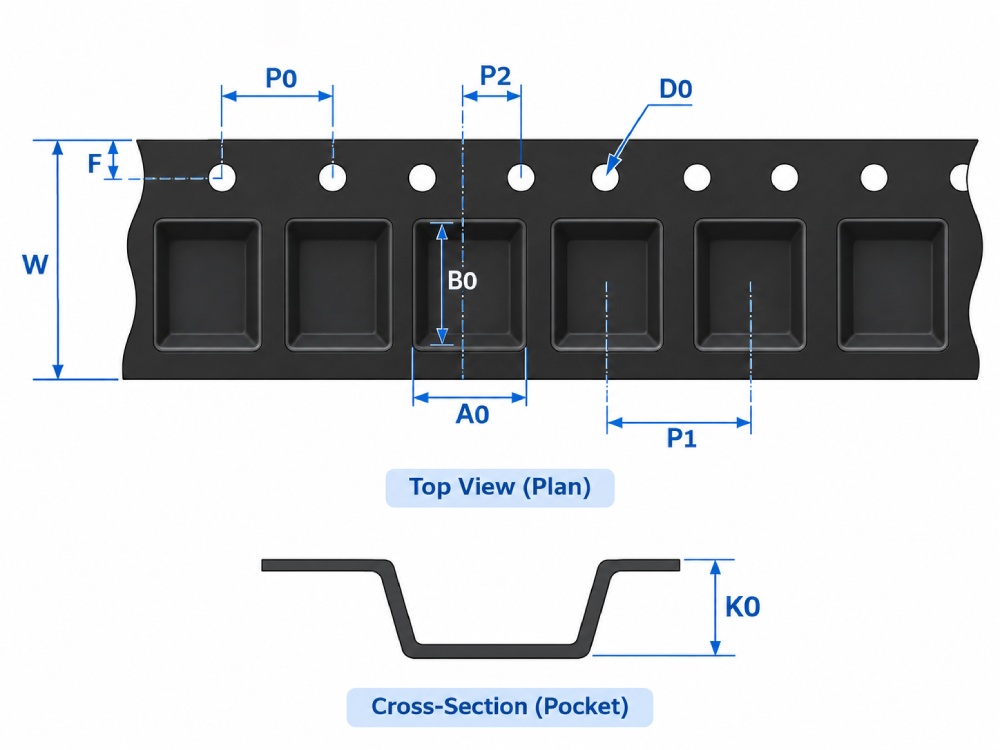
The primary embossed pocket dimensions are:
-
A0: Pocket dimension along one specified cavity direction.
-
B0: Pocket dimension perpendicular to A0.
-
K0: Pocket depth.
These dimensions must be interpreted according to the approved drawing, including the specified measurement locations and reference surfaces.
A suitable inspection procedure is to:
-
Place the sample in the measuring fixture with the correct orientation.
-
Identify the required A0 and B0 measurement locations.
-
Measure pocket depth using an appropriate method.
-
Repeat the measurements at the specified sample positions.
-
Compare the results with the approved dimensional limits.
The inspector should pay attention to differences between pockets, particularly when the sample includes material produced over several forming cycles.
A pocket may meet its main dimensional requirements while still showing damaged corners, excessive localized thinning, or surface defects. Dimensional and visual inspection should therefore complement each other.
Check Pocket Pitch and Sprocket-Hole Position
Pitch and registration influence how accurately the tape advances through automated handling equipment.
Important dimensions include:
-
P1: Distance between successive pocket centerlines along the tape.
-
P0: Pitch between successive sprocket-hole centers.
-
D0: Sprocket-hole diameter.
-
P2: Longitudinal relationship between the sprocket-hole pattern and pocket position.
-
F: Lateral distance between the sprocket-hole centerline and pocket centerline.
The approved drawing defines the measurement references and applicable limits.
During first-piece inspection, measure the relevant dimensions across the required sample positions. Where specified, evaluate cumulative spacing over multiple pitches rather than relying only on a single interval.
Differences between the pocket pattern and sprocket-hole pattern may indicate an issue with feeding, indexing, tooling alignment, or punching setup.
Incorrect registration can affect pocket positioning during automated component loading and subsequent feeder operation.
Compare Results with the Approved Drawing
Every critical dimension should be evaluated against the correct engineering specification.
The inspector should confirm:
-
The drawing revision matches the production order.
-
The correct measurement reference is being used.
-
The measuring equipment has adequate capability for the specified limits.
-
Actual readings are recorded where required.
-
All applicable acceptance criteria have been satisfied.
The EIA-481-F standard provides industry requirements for carrier taping of surface-mount components. However, the applicable acceptance criteria must be identified from the approved product specification, contractual requirements, and relevant standard provisions.
EIA-481 should not be treated as a substitute for a factory-specific first-piece inspection plan.
For a broader explanation of dimensional and functional inspection, refer to carrier tape testing methods.
Visual and Forming Quality Checks Before Production Release
Not every forming problem can be identified through dimensional measurement alone.
A visual inspection helps detect surface damage, incomplete forming, abnormal hole geometry, and other defects that may require further investigation.
Inspect the sample under suitable lighting, using magnification when necessary.
Inspect Pocket Walls, Corners, and Bottom Surfaces
Examine the formed pockets for:
-
Incomplete or uneven forming.
-
Distorted pocket walls.
-
Cracks around corners or transition areas.
-
Localized whitening or unusual deformation.
-
Irregular pocket openings.
-
Damaged pocket bottoms.
-
Visible contamination or embedded particles.
Some reduction in wall thickness is expected when thermoplastic film is stretched into a pocket.
The engineering concern is whether the finished pocket retains sufficient structural integrity and meets the approved design requirements.
Visual appearance alone cannot establish the actual remaining wall thickness. If abnormal thinning is suspected, additional measurement may be necessary.
For more detail, see carrier tape pocket wall thinning and forming checks.
Inspect Sprocket Holes and Tape Edges
Sprocket holes should have the required geometry and positioning for reliable indexing.
Inspect for irregular hole shapes, damaged edges, punching burrs, and plastic debris.
Also examine the tape edges for tearing, uneven cutting, scratches, or other handling damage.
Visible hole deformation may indicate punching-tool wear, material displacement, or alignment problems. The actual cause should be established through further inspection rather than assumed from appearance alone.
Check Tape Curl, Camber, and Surface Condition
The first-piece sample should also be examined for abnormal tape deformation.
Curl refers to the tendency of the tape to bend away from a flat condition, while camber describes sideways deviation along its length.
Depending on the severity and application, these conditions may affect tracking through guides, packaging equipment, or feeders.
Inspect the tape on an appropriate reference surface or with the specified measurement method.
Compare the results with the applicable acceptance criteria. If visible deformation appears excessive, record the condition and investigate the relevant material-handling or process settings.
Additional First-Piece Checks for Loaded Tape-and-Reel Packaging
The preceding checklist focuses primarily on empty embossed carrier tape production.
When a production operation also includes component loading, cover tape sealing, or reel winding, additional inspections may be necessary.
These checks belong to the downstream packaging process and should not automatically be included in every empty carrier tape forming inspection.
Verify Component Loading and Cover Tape Condition
For loaded carrier tape, inspectors may need to confirm:
-
Correct component identification.
-
Approved component orientation.
-
Proper seating inside the pocket.
-
No missing or visibly damaged components.
-
Correct cover tape identification and alignment.
-
Acceptable seal appearance and continuity.
-
Peel-force performance where required.
Cover tape must provide suitable component retention while allowing controlled removal during automated feeding.
When peel-force testing is required, use the approved test method and acceptance limits for the specific packaging configuration.
A visually acceptable seal does not necessarily demonstrate compliant peel-force performance.
Confirm Reel and Feeder Compatibility
Additional checks may include reel identification, tape winding direction, tracking, winding condition, and packaging traceability.
A feeder trial may also be required for certain product approvals or process changes.
Such verification should use the applicable packaging and equipment requirements rather than an assumed universal feeder setting.
What to Do When the First-Piece Inspection Fails
A failed first-piece inspection means the current setup has not met the conditions for production release.
The immediate objective is to prevent potentially nonconforming material from entering continuous production while identifying the cause of the problem.
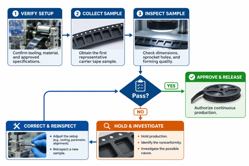
Hold Production and Identify the Nonconformity
When a characteristic fails inspection, the responsible personnel should follow the approved nonconformance procedure.
The general response includes:
-
Hold production release for the affected setup.
-
Record the failed characteristic and actual measurement or observation.
-
Identify the sample and potentially affected material.
-
Notify the responsible production or quality personnel.
-
Investigate the problem before making corrective adjustments.
If material has already been produced, the potentially affected quantity should be determined using the available production records and applicable inspection history.
Material disposition should follow the authorized quality procedure.
Correct the Setup and Repeat the Relevant Checks
The next step is to identify the likely process condition responsible for the nonconformity.
| Inspection failure | Possible investigation area | Verification after correction |
|---|---|---|
| Pocket depth variation | Forming conditions or tooling | Recheck K0 and pocket geometry |
| Incorrect pocket pitch | Feeding or indexing setup | Recheck P1 |
| Pocket-to-hole misalignment | Registration or punching setup | Recheck P2 and F |
| Distorted sprocket holes | Punching tool or material behavior | Recheck hole geometry |
| Incomplete pocket forming | Forming conditions or tool condition | Reinspect pocket dimensions and walls |
| Excessive curl or camber | Material handling, tension, or process conditions | Recheck applicable deformation criteria |
These examples identify possible areas for investigation, not confirmed root causes.
After corrective action, a new representative sample should be inspected under the corrected operating conditions.
Any related characteristics affected by the adjustment should also be verified.
Avoid Releasing Material Based on One Corrected Reading
A single acceptable measurement does not necessarily demonstrate that the entire setup is ready for production.
For example, correcting pocket depth may affect other forming characteristics. Similarly, adjusting indexing may require rechecking the relationship between pocket pitch and sprocket-hole position.
The repeat inspection should cover the failed characteristic and any other potentially affected features identified by the control plan.
Production may proceed only after the applicable inspection requirements are satisfied and the authorized release decision is recorded.
Record First-Piece Results and Authorize Production
First-piece inspection should produce traceable evidence of the setup condition and inspection outcome.
A clear record allows production and quality personnel to identify which setup was checked, what was measured, and whether the line was approved.
What a First-Piece Inspection Record Should Include
A practical inspection record may contain the following information:
| Record field | Information to document |
|---|---|
| Date and shift | Inspection date and production shift |
| Production order | Work order or batch reference |
| Product identification | Carrier tape part number |
| Drawing revision | Approved specification version |
| Machine and tooling | Equipment and tool identification |
| Material lot | Raw material batch reference |
| Inspection trigger | Shift start, changeover, restart, or adjustment |
| Sample identification | Traceable first-piece sample reference |
| Inspection results | Actual values and visual findings |
| Acceptance status | Pass, Fail, Hold, or N/A as applicable |
| Corrective action | Action taken when a failure occurs |
| Inspector | Person completing the inspection |
| Release authorization | Approval according to the quality procedure |
The actual record may be paper-based or electronic, depending on the production management system.
The most important requirement is that the record provides enough information to support an understandable and traceable release decision.
Production Release and Continued Monitoring
The person authorized by the production control procedure should review the results before continuous manufacturing is released.
Where an independent quality check is required, the approval process should include that verification.
After release, periodic in-process inspections remain necessary.
Machine wear, material variation, operating conditions, and other process factors can change during a production run.
First-piece approval establishes an acceptable starting condition; in-process monitoring helps confirm that the condition remains controlled.
Frequently Asked Questions
Does EIA-481 specify how many pockets must be checked during shift-start inspection?
EIA-481 establishes requirements for carrier taping and related packaging characteristics, but it should not be interpreted as providing one universal first-piece sampling quantity for every factory.
The number of pockets, sample length, inspection locations, and release criteria should follow the applicable production control plan and customer requirements.
Can carrier tape pass first-piece inspection but develop defects later in the shift?
Yes. First-piece inspection verifies a representative sample at a particular time.
Subsequent changes in tooling condition, material behavior, feed alignment, or forming parameters may affect production quality. This is why continued in-process inspection and appropriate reaction procedures are necessary.
Is automated vision inspection enough to approve the first carrier tape sample?
Automated vision systems can be useful for checking visible geometry, sprocket-hole positioning, and certain forming defects.
However, not every system can measure pocket depth, wall thickness, material properties, or other characteristics that may be required for approval.
The inspection method must be validated for the characteristic being measured, and additional testing may be necessary.
Should a new material roll always trigger another first-piece inspection?
Not necessarily.
The required verification depends on the material grade, lot change, process risk, and approved control plan.
Some material changes may require identification checks, while others may call for additional dimensional or process verification. A different material formulation or thickness can also affect forming behavior.
The decision should follow documented production requirements.
Final Check Before Releasing the Carrier Tape Production Line
A reliable carrier tape first-piece inspection connects machine setup verification with measurable product quality.
Before continuous production begins, the responsible team should confirm that the correct materials and tooling are installed, representative samples meet approved dimensional and visual requirements, inspection results are documented, and release authorization is complete.
First-piece approval is the starting point of production control, not a replacement for continued monitoring.
For manufacturers evaluating carrier tape specifications, material options, or custom pocket designs, reviewing the available carrier tape products can help identify the technical information needed for further engineering discussion.



 Emial
 John Mr