





Carrier Tape Pocket Corner Defects: Causes & Inspection
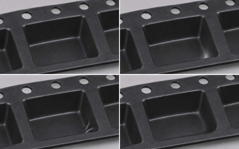
Pocket corner defects in embossed carrier tape include cracks, stress whitening, wrinkles, and localized deformation around the formed pocket corners. These abnormalities may originate from tooling geometry, material behavior, forming conditions, or handling after production.
Not every visible mark indicates structural failure. However, damaged corners can affect pocket integrity, component positioning, and packaging reliability. Identifying the defect type, inspecting its location, and verifying the possible cause are essential before deciding whether the affected carrier tape is acceptable.
This guide explains how to recognize common pocket corner defects, perform practical inspections, investigate forming-related causes, and verify corrective actions.
Common Pocket Corner Defects in Embossed Carrier Tape
Pocket corner defects can occur at the opening, along vertical wall intersections, or near the bottom corner radius. Their appearance depends on the material, pocket geometry, forming process, and the stage at which damage develops.
Different defects may look similar during a quick visual inspection. Engineers should therefore examine the affected location carefully before identifying the problem.
Corner Cracks and Localized Fractures
Corner cracks appear as fine fracture lines, splits, or localized breaks in the formed plastic. They may develop near the pocket bottom, along a vertical corner, or where the pocket wall transitions into another surface.
A crack can be difficult to identify on transparent carrier tape, particularly when reflections or surface scratches are present.
During inspection, engineers should check whether the visible line:
-
Extends through the material or remains on the surface.
-
Continues across adjacent pocket surfaces.
-
Appears repeatedly at the same corner position.
-
Changes appearance under different lighting angles.
Confirmed fractures may compromise pocket integrity and component protection. Suspected cracks should be contained for further examination rather than accepted based only on overall pocket dimensions.
Stress Whitening and Discoloration
Stress whitening appears as a white, cloudy, or lighter-colored region near a pocket corner. It can develop when local deformation changes the material‘s optical appearance.
Some thermoplastic materials exhibit whitening under mechanical stress or excessive stretching. However, film composition, surface texture, and lighting conditions can also influence visible color differences.
Whitening does not automatically mean that the pocket is cracked or structurally unacceptable.
Engineers should compare the affected area with approved samples and investigate whether the mark is associated with deformation, cracking, or other changes in material condition.
Corner Wrinkles and Material Folds
Corner wrinkles appear as raised lines, creases, or localized folds within the pocket geometry.
Unlike ordinary surface marks, wrinkles may change the internal shape of the pocket. A pronounced fold can interfere with component seating, particularly when the component has limited clearance.
During inspection, check whether the wrinkle extends into the component-supporting area or changes the pocket opening.
The presence of a wrinkle should also be evaluated against the approved pocket shape rather than judged by appearance alone.
Incomplete or Distorted Corner Formation
Incomplete corner formation occurs when the plastic does not reproduce the intended pocket geometry.
Typical observations include rounded or poorly defined corners, uneven sidewalls, local collapse, and asymmetrical pocket shapes.
These conditions can affect the available space inside the pocket, even when the overall tape width and pitch remain acceptable.
Engineers should compare the affected pocket with the approved drawing, paying particular attention to the cavity dimensions A0 and B0, pocket depth K0, and any specified corner geometry.
Pocket Corner Defect Comparison
| Defect type | Typical appearance | Main inspection concern |
|---|---|---|
| Corner cracking | Fine lines, splits, or fractures | Structural integrity |
| Stress whitening | White or cloudy corner areas | Possible local stress or material change |
| Corner wrinkles | Raised folds or creases | Pocket shape and component clearance |
| Incomplete formation | Poorly defined or rounded corners | Dimensional conformity |
| Local deformation | Collapsed or asymmetrical corners | Component positioning and retention |
These observations provide an initial classification. Final acceptance depends on the approved design requirements and supporting inspection evidence.
How to Inspect Pocket Corner Defects Step by Step
A reliable pocket corner inspection should identify the abnormality, record its position, and determine whether additional verification is necessary.
The following procedure provides a practical framework for production quality checks and engineering investigations.
Step 1: Identify and Record the Defect Location
Begin by locating the affected pocket and identifying the exact corner where the abnormality appears.
Record the tape travel direction and pocket orientation so that inspection results can be compared consistently.
Check whether the defect appears:
-
At the pocket opening or upper corner.
-
Along the vertical pocket wall intersection.
-
Near the bottom corner radius.
-
At the same position across consecutive pockets.
Also record the affected material lot, production batch, and inspection stage when available.
A defect that repeatedly appears at the same corner may suggest a localized process or tooling condition, although further evidence is required to establish the cause.
Step 2: Examine the Corner Under Suitable Lighting
Inspect the affected pocket under consistent lighting conditions.
Start with a visual examination, then use a magnifier or optical microscope if the abnormality cannot be clearly distinguished.
Angled reflected light can help reveal surface folds, scratches, and fracture-like lines. For suitable transparent or translucent materials, transmitted lighting may provide additional information.
The objective is to determine the observable condition without damaging the pocket.
Avoid interpreting a bright reflection, surface mark, or color variation as a confirmed crack without supporting evidence.

Step 3: Compare Defective and Approved Pockets
Compare the suspected defect with an approved reference sample of the same pocket design and material.
Examine the corner shape, surface condition, and symmetry.
Pay attention to whether the abnormality appears consistently across several pockets or occurs only occasionally.
Photographs should use comparable viewing angles and lighting whenever possible.
This comparison helps distinguish normal material appearance from a change in the forming result.
Step 4: Perform Additional Checks When Needed
Visual inspection may not provide enough information to determine the severity of a defect.
If the corner appears distorted, measure the relevant pocket dimensions using an appropriate method.
If structural weakening is suspected, additional examination of the affected region may be necessary.
For localized material thinning concerns, refer to the existing guide on carrier tape pocket wall thickness measurement.
When component clearance may be affected, perform an appropriate fit check using the actual component or an approved reference.
The inspection record should distinguish confirmed observations from suspected causes.
What Causes Pocket Corner Defects During Carrier Tape Forming?
Pocket corner defects can result from several interacting factors. The same visible condition may arise from different material or processing problems.
An effective investigation should consider the pocket design, tooling condition, film properties, forming parameters, and downstream handling.
Pocket Geometry and Tooling Design
Pocket geometry directly influences how the plastic film deforms during forming.
Deep cavities, abrupt wall transitions, or small corner radii may increase localized deformation demands, depending on the material and forming method.
Tooling wear, surface damage, misalignment, or inconsistent cavity geometry can also contribute to abnormal corner formation.
Engineers should examine whether the defect occurs at a repeatable position corresponding to a particular tooling feature.
Where a corner radius is suspected, modifying the geometry may be considered. However, any design change must preserve component clearance, orientation, and the approved pocket dimensions.
Forming Temperature and Heating Uniformity
The temperature of the plastic film influences its ability to deform into the required pocket shape.
If the material is insufficiently heated for the selected process, forming may become inconsistent, particularly around demanding corner geometries.
Uneven heating can also cause different areas of the film to respond differently during deformation.
Excessive heating may produce other problems, including reduced shape stability or unwanted material movement.
Engineers should review the heating conditions, equipment stability, and actual film temperature where measurement is available.
A heater setpoint alone does not confirm the temperature of the material during forming.
Forming Pressure, Vacuum, and Timing
Pressure, vacuum, and forming timing influence how the film contacts the tooling and develops the required cavity shape.
The relevant variables depend on the equipment and forming method.
Insufficient or inconsistent forming action may contribute to incomplete corner definition. Poor venting, vacuum irregularities, or synchronization problems may also affect the finished pocket.
However, increasing pressure or extending the forming cycle is not automatically the correct solution.
Adjustments should be made through controlled trials, followed by inspection of the resulting pocket geometry and surface condition.
Material Properties and Film Conditions
Different carrier tape materials respond differently to heating, stretching, cooling, and tooling contact.
Common material families include polystyrene (PS), polyethylene terephthalate (PET), polycarbonate (PC), and acrylonitrile butadiene styrene (ABS).
Their forming behavior depends on the specific grade, film construction, and processing conditions rather than the polymer name alone.
When defects begin after a material change, engineers should review:
-
Material grade and supplier specifications.
-
Incoming film thickness consistency.
-
Relevant forming characteristics.
-
Material lot changes.
-
Conductive or anti-static layer construction, where applicable.
For conductive or ESD-sensitive carrier tape, material changes may also require additional electrical performance verification.
A different material should not be selected solely because it produces a better-looking corner during an initial forming trial.
Cooling, Tool Release, and Subsequent Handling
Not every pocket corner defect originates during the initial forming stage.
Cooling behavior and tool release conditions can influence the final pocket shape. Mechanical contact during removal, transport, or winding may introduce additional damage.
For example, a pocket may appear acceptable immediately after forming but show localized deformation after subsequent handling.
Comparing samples collected at different production stages can help determine when the abnormality first appears.
This distinction is important because changing forming parameters will not resolve damage caused entirely by a downstream operation.
Troubleshooting Pocket Corner Defects by Their Appearance and Location
The position and recurrence of a defect often provide useful clues about where an investigation should begin.
Rather than adjusting multiple process variables immediately, engineers should first examine the defect pattern.
The Same Corner Is Defective Across Consecutive Pockets
When the same relative corner shows a repeated abnormality, examine the corresponding tooling geometry, cavity condition, and local forming behavior.
Compare samples from different production intervals to determine whether the condition is stable or develops over time.
A repeated pattern supports a focused investigation but does not independently prove a tooling problem.
Corner Defects Appear Across Several Pocket Positions
When similar abnormalities occur across multiple locations, review common process factors.
These may include incoming film conditions, heating uniformity, forming consistency, or material changes.
Comparing defect distribution with available process records can help narrow the investigation.
Defects Appear After a Setup or Material Change
If corner defects begin after a production adjustment, compare the current configuration with the previously approved setup.
Review changes involving tooling, material, heating, forming settings, or maintenance activities.
Preserve defective samples and relevant production records before making additional adjustments.
Corners Become Damaged After Forming
When a defect is not visible immediately after forming but appears later, inspect the downstream handling sequence.
Compare samples before and after operations such as tape transport, reel winding, or packaging.
Look for contact points or mechanical conditions that could explain the damage.
Pocket Corner Defect Troubleshooting Matrix
| Observed defect | Possible investigation area | Recommended first check |
|---|---|---|
| Repeated cracking at one corner | Tooling geometry or localized forming conditions | Inspect corresponding tooling features and corner positions |
| Whitening near corner transitions | Material response or forming conditions | Compare approved samples and examine for structural damage |
| Wrinkles or poorly defined corners | Forming action, film behavior, or tooling geometry | Review formed shape and relevant process records |
| Distortion across multiple pockets | Heating, material, or process consistency | Compare affected pockets and production conditions |
| Damage after winding | Mechanical contact or handling | Compare samples before and after winding |
| Defects after a material change | Material grade or incoming film variation | Compare material specifications and retained samples |
The matrix identifies possible investigation paths, not confirmed root causes. Final conclusions should be supported by inspection results and controlled verification.
How to Decide Whether a Pocket Corner Defect Is Acceptable
A visible corner abnormality does not automatically mean that the entire carrier tape batch must be rejected.
However, acceptance should be based on documented requirements rather than appearance alone.
Engineers should distinguish cosmetic changes, dimensional deviations, and confirmed structural damage.
Cosmetic Appearance Versus Structural Damage
Minor discoloration or surface marks may be acceptable when they do not violate the agreed specifications or affect the intended function.
In contrast, a confirmed fracture, puncture, or other loss of pocket integrity requires evaluation against the applicable rejection criteria.
Suspected structural defects should be contained until the relevant inspection and disposition decision is completed.
Whitening should not be treated as equivalent to cracking without further evidence.
Verify Component Fit and Packaging Function
A pocket may appear dimensionally consistent while still having a localized problem that affects the component.
Where relevant, engineers should evaluate whether the defect influences:
-
Component seating and intended orientation.
-
Available clearance inside the pocket.
-
Component retention during handling.
-
Vertical component removal.
-
Pocket stability during tape feeding.
If local deformation changes the effective cavity geometry, check the applicable A0, B0, and K0 dimensions.
For more information on measurement methods, see How to Measure Carrier Tape Dimensions Correctly for SMT.
If deformation extends toward the sealing area, verify that the cover tape can be applied without compromising the approved seal geometry.
For the same reason, a visual check alone may not be sufficient where the application requires functional verification.
Apply Approved Acceptance Requirements
Standards such as EIA-481-F and IEC 60286-3:2022 address technical requirements for tape packaging of electronic components.
However, these references should not be interpreted as providing a universal acceptance limit for every type of visible pocket corner defect.
The final decision should consider the applicable standard requirements, approved drawings, customer specifications, and validated inspection criteria.
Where acceptance requirements are unclear, engineering review is necessary before releasing affected material.
Corrective Actions and Verification Before Production Release
Once a pocket corner defect has been identified, corrective action should address the verified cause rather than the appearance alone.
A structured process helps prevent repeated adjustments that create new forming problems.
Contain the Affected Material
Identify the production lots, reels, or tape sections potentially affected by the problem.
Preserve representative samples showing the abnormality and, where possible, approved reference samples.
Review production records to establish when the defect first appeared.
The inspection scope and material disposition should follow the applicable quality procedure.
Investigate and Test the Suspected Cause
Begin with the strongest available evidence.
If defects are concentrated at one corner, review local tooling and forming conditions. If they appear after a material change, examine the incoming film records.
Conduct controlled trials using appropriate process variables.
Where practical, change one factor at a time and document its effect on the defect.
Avoid introducing several unverified adjustments simultaneously, as this makes it difficult to determine which change produced the improvement.
Verify the Corrected Pocket Quality
After corrective action, inspect representative samples using the same criteria applied to the original defect.
Confirm that the abnormality has been eliminated or reduced to an acceptable condition.
Verify relevant pocket dimensions, component fit, and packaging performance as required.
Where necessary, conduct additional checks during downstream handling or feeder operation.
Production release should follow the established approval procedure, supported by inspection records and any required engineering authorization.
What Information Should Be Provided for a Pocket Corner Defect Review?
A clear engineering review begins with accurate information about the affected carrier tape.
When requesting technical support, prepare the following information where available:
-
Carrier tape specification: Tape width, pocket pitch, A0, B0, K0, and relevant drawing revision.
-
Material details: Material type, grade, construction, and lot identification.
-
Defect photographs: Clear images showing the affected corners and their locations.
-
Defect pattern: Whether the problem is continuous, intermittent, or concentrated at a particular position.
-
Production information: Relevant setup changes, material changes, or processing records.
-
Component details: Component drawing or physical sample when fit and orientation are involved.
-
Inspection results: Available dimensional checks and observations from approved reference samples.
This information helps engineers determine whether the problem is more likely associated with pocket design, material behavior, forming conditions, or subsequent handling.
For additional background on automated inspection capabilities, see the Carrier Tape Inspection Machine Guide.
Frequently Asked Questions About Pocket Corner Defects
Are white marks on carrier tape pocket corners always defects?
No. White or cloudy marks may result from local material deformation, surface characteristics, or lighting effects. Their presence does not automatically confirm cracking or inadequate wall thickness. Engineers should compare affected pockets with approved samples and perform additional checks when structural damage is suspected.
Can carrier tape pass dimensional checks but still have damaged pocket corners?
Yes. Overall pocket dimensions do not describe every aspect of localized structural integrity. A pocket may meet its measured A0, B0, and K0 requirements while having a crack or other damage at a corner. Visual and functional inspection may therefore be necessary in addition to dimensional measurement.
Can reel winding damage corners that looked acceptable after forming?
Yes, mechanical contact or unsuitable handling conditions can potentially introduce damage after forming. However, the cause should be verified. Comparing samples collected before and after winding helps determine whether the abnormality originated during forming or developed during a later operation.
Does changing the carrier tape material always solve corner defects?
No. Pocket corner defects may involve tooling geometry, forming conditions, material properties, or downstream handling. Changing the material without identifying the underlying cause may introduce additional dimensional or functional problems. Any replacement material should be evaluated against the approved pocket design and applicable packaging requirements.
Conclusion: Preventing Repeated Pocket Corner Defects
Pocket corner defects in embossed carrier tape should be evaluated through consistent visual inspection, defect-location records, and appropriate engineering checks.
Cracking, whitening, wrinkles, and deformation may appear similar but can have different causes and functional consequences. Effective troubleshooting begins by identifying the actual defect, reviewing relevant production conditions, and verifying corrective actions against approved specifications.
For recurring corner problems, clear photographs, pocket drawings, and representative samples can help support a more focused engineering review.
Jiushuo provides embossed and custom carrier tape options for electronic component packaging. Sharing the component requirements and observed pocket defects can help determine whether further inspection, tooling evaluation, or pocket design adjustments are appropriate.



 Emial
 John Mr