

Component Rotation at Pick-Up: Pocket & Feeder Checklist
Component rotation at the SMT pick-up position can cause inaccurate nozzle engagement, vision recognition errors, rejected components, and unstable placement performance. However, a rotated component does not automatically indicate a carrier tape defect.
The first step is to determine when the component changes orientation: before cover tape removal, during feeder indexing, or after nozzle contact. Engineers should then document the pocket condition, component orientation, feeder configuration, and relevant machine observations.
This guide explains how to collect that evidence, distinguish pocket-related findings from feeder-related issues, and prepare a technical report for further investigation.
1. What Counts as Component Rotation at the Pick-Up Position?
Component rotation occurs when an electronic component changes its angular orientation relative to the expected position inside a carrier tape pocket or at the machine‘s pickup location.
The expected orientation should be established from the approved component packaging drawing, including the feed direction and polarity or pin-1 reference where applicable.
Not every positioning abnormality is rotation. Engineers should distinguish between four conditions:
|
Condition |
Description |
Typical Observation |
|---|---|---|
|
Rotation |
Component turns within its horizontal plane |
Pin-1 mark or component edge changes angle |
|
Offset |
Component shifts away from its expected position |
Component center is displaced |
|
Tilt |
Component does not rest flat on its intended support |
One side or corner appears raised |
|
Flipping |
Component turns over or reverses its face orientation |
Incorrect component face is presented |
These conditions can occur independently or together.
For example, a component may remain parallel to the pocket walls but move toward one corner. This is primarily a positional offset. Another component may remain centered while its body rotates relative to the pocket axis.
The distinction matters because each symptom may require different measurements and feeder observations.
Establish the Expected Component Orientation
Before recording a rotation problem, identify a consistent orientation reference.
For polarized devices, this may be a pin-1 marking, package notch, or termination arrangement. For components without visible polarity markings, engineers may need to use a package drawing or an approved orientation reference.
The sprocket-hole side and carrier tape feed direction should appear in the inspection record.
A machine vision angle alone is insufficient to confirm that a component physically rotated. The reported angle must be interpreted against the camera coordinate system, programmed component orientation, and any automatic correction applied by the machine.
2. At Which Stage Does Component Rotation First Appear?
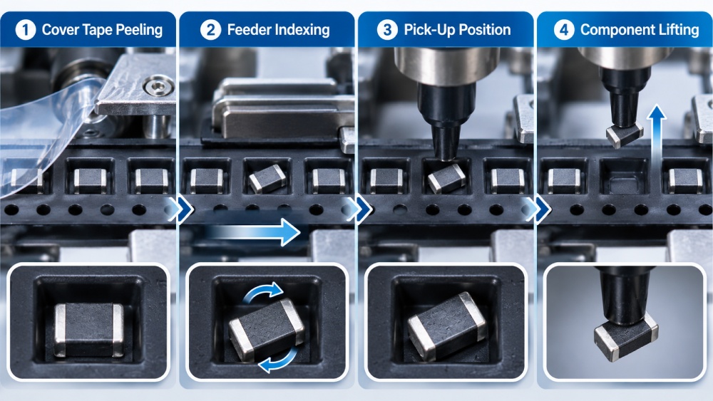
Identifying the stage at which rotation first becomes visible helps narrow the investigation.
A component found rotated at the pickup position may have been incorrectly oriented during packaging, moved during cover tape separation, shifted during feeder indexing, or changed orientation during nozzle engagement.
The investigation should follow the component through the feeding process without disturbing the original setup unnecessarily.
Before Cover Tape Removal
If the component is visible through a transparent cover tape, inspect its orientation before the pocket enters the feeder‘s peeling area.
Check whether the component is already misaligned or shows signs of unstable seating.
When the cover tape is opaque, the component cannot be directly observed without an appropriate inspection method. In such cases, review available packaging inspection records or inspect retained samples under a controlled procedure.
Record the reel number, component lot, and approximate pocket location before removing any material.
After Cover Tape Peeling and Feeder Indexing
Observe the component immediately after the cover tape separates from the carrier tape.
Pay attention to three possible events:
-
Movement during peeling: The component changes position as the cover tape is removed.
-
Movement during indexing: The component rotates as the feeder advances the carrier tape.
-
Movement after indexing: The component changes orientation while the exposed pocket is stationary.
These observations should be recorded separately.
For very small components, feeder vibration and the distance between the peeling position and pickup position can influence component stability. Nexperia has documented such concerns for its DSN0402B-2 package, although its application-specific findings should not be treated as universal machine settings.
During Nozzle Contact and After Pick-Up
If the component remains correctly oriented before pickup, examine the nozzle engagement stage.
Review whether the nozzle contacts the intended surface, whether pickup is centered, and whether the component shifts while being lifted.
Where available, compare images captured before and after nozzle contact.
Also distinguish physical rotation from intentional rotation commanded by the placement program or calculated through the machine‘s vision correction system.
The most useful initial finding is not simply that rotation occurred, but the earliest stage at which the orientation changed.
3. What Evidence Should Be Recorded Before Troubleshooting?
A useful SMT component rotation report should allow another engineer to identify the affected material, understand the machine setup, and review the observed failure without relying entirely on verbal explanations.
Evidence should be collected before changing feeder settings, replacing parts, or removing the affected reel whenever practical and safe.
Record Reel and Component Identification
Start with the material identification:
-
Component manufacturer, part number, and production lot.
-
Carrier tape part number and batch identification.
-
Cover tape identification, where available.
-
Reel label information and traceability reference.
-
Packaging drawing or approved specification revision.
-
Approximate location of the affected pocket on the reel.
The production record should also identify the SMT machine, feeder position, and date of the observation.
This information helps determine whether the problem is associated with a particular component lot, packaging batch, or production setup.
Capture Photos and Video with Consistent References
Photographs should show both the local defect and its surrounding context.
A useful evidence set includes an overview of the feeder, a close-up of the component inside its pocket, and an image showing the relationship between the component and the expected pickup position.
Whenever possible, use the same viewing direction for comparison images. Mark the tape feed direction and sprocket-hole side so that the component orientation can be interpreted consistently.
Short video recordings may provide additional evidence when rotation occurs during peeling or indexing. Record footage only through approved machine monitoring or safe inspection procedures.
Avoid manually disturbing components before their original positions have been documented.
Preserve the Original Feeder and Machine Conditions
The equipment record should include the feeder model, identification number, installed position, selected tape pitch, and relevant pickup settings.
Where accessible, preserve machine recognition images, vacuum observations, feeder alarms, and component rejection logs.
Any adjustment made after the initial observation should be recorded separately, including the change made and the result.
Minimum Component Rotation Evidence Log
|
Evidence Field |
Information to Record |
|---|---|
|
Event ID |
Unique investigation reference |
|
Component identification |
Part number, manufacturer, and lot |
|
Carrier tape |
Part number, batch, and reel ID |
|
Feeder |
Model, identification number, and slot |
|
Observation stage |
Before peeling, after indexing, or after pickup |
|
Orientation finding |
Expected and observed component position |
|
Pocket condition |
Visible clearance, support, or deformation |
|
Machine response |
Pickup failure, vision rejection, or alarm |
|
Supporting evidence |
Photograph, video, and log references |
|
Initial assessment |
Observed facts and possible causes |
The purpose of this record is to preserve comparable evidence, not to establish a root cause before the investigation begins.
4. How to Document Carrier Tape Pocket Findings
Carrier tape pocket inspection should focus on how the component fits, rests, and moves inside the cavity.
A pocket may meet its nominal dimensional requirements but still require further evaluation if the component moves unexpectedly during feeding.
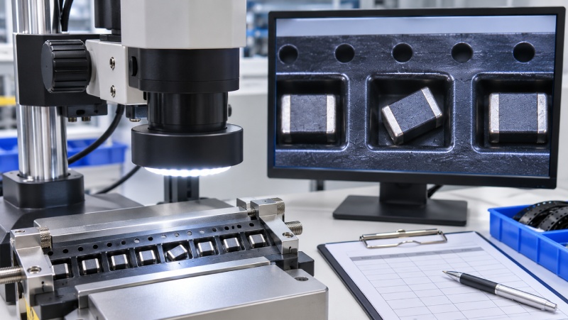
Compare Component Dimensions with A0, B0, and K0
Start with the approved component outline and carrier tape drawing.
The principal pocket dimensions are:
-
A0: Pocket dimension accommodating the component width.
-
B0: Pocket dimension accommodating the component length.
-
K0: Pocket depth accommodating the component height.
These dimensions must be interpreted using the drawing‘s defined orientation and measurement references.
Use appropriate optical or dimensional inspection equipment to compare the actual pocket geometry with the approved specification.
Record whether the component has excessive movement, restricted clearance, or inconsistent seating. Consider both the component‘s dimensional variation and the pocket‘s actual geometry.
Nominal A0 and B0 values alone do not establish whether a component can rotate. Pocket corner geometry, component shape, support features, and the available movement within the cavity may also matter.
There is no single acceptable clearance applicable to every component. The evaluation should follow the approved packaging design and its intended feeding conditions.
Inspect Pocket Support and Contact Features
Inspect the pocket walls, corners, and bottom support area.
Look for visible deformation, uneven forming, damaged corners, material projections, or contamination that could affect component positioning.
Check whether the component rests consistently on its intended support surfaces.
If an abnormal condition is observed, photograph the affected pocket and compare it with an approved reference pocket.
Avoid manually forcing the component into position before recording the original condition.
Check Pocket Position Relative to Feeder Indexing
When rotation is accompanied by inconsistent pocket presentation, inspect the carrier tape‘s positional features.
Relevant dimensions may include tape width (W), pocket pitch (P1), sprocket-hole pitch (P0), and pocket-to-sprocket registration dimensions such as P2 and F, where applicable.
The feeding-hole diameter, commonly designated D0, may also require inspection.
These measurements help determine whether the pocket is being presented consistently to the feeder mechanism.
For broader dimensional troubleshooting, refer to the approved carrier tape drawing and the applicable tape packaging specifications.
5. What Feeder and Pick-Up Findings Should Be Documented?
Feeder-related findings are essential because component rotation may result from interactions between the packaging material, feeder mechanism, and pickup system.
The inspection should distinguish tape movement from component movement and identify whether the pickup mechanism introduces any additional instability.
Feeder Indexing and Tape Support
Record the installed feeder model, feeder identification number, programmed tape pitch, and relevant equipment configuration.
Observe whether the carrier tape moves smoothly through the guide and reaches a repeatable pickup position.
Check for visible tracking problems, damaged sprocket holes, irregular indexing, or interference between the embossed pockets and feeder support features.
Also inspect the approved tape guide and support arrangement where accessible.
Some feeder designs include features intended to improve stable feeding and compensate for pickup-position variation. JUKI, for example, describes vibration suppression and automatic pickup-position correction in its electric feeder series. These functions are equipment-specific and should not be assumed to exist on every feeder.
Cover Tape Removal and Component Stability
Observe how the cover tape separates from the carrier tape.
Record whether peeling appears smooth or whether the cover tape wrinkles, lifts irregularly, or contacts the exposed component.
The distance between the peeling point and pickup position may be relevant, especially for small or lightweight components.
If rotation becomes visible immediately after peeling, preserve video evidence and compare the behavior with an approved setup.
Peel-force measurements may support the investigation, but they should not be used alone to identify the cause of rotation.
See Carrier Tape Peel Force Explained for Stable SMT Assembly for additional information about cover tape separation and feeding stability.
Nozzle, Vacuum, and Vision Findings
If the component remains stable until pickup, examine the machine‘s pickup process.
Record nozzle identification, pickup position, relevant height settings, and available vacuum observations.
Review whether the nozzle contacts the intended component surface and whether the component shifts during lifting.
Machine recognition images may help identify positional offset or angular deviation. However, any calculated orientation correction must be distinguished from physical movement.
The findings should be evaluated against the relevant machine manufacturer‘s specifications rather than universal assumptions about nozzle pressure, vacuum level, or pickup speed.
6. How to Distinguish Pocket-Related Findings from Feeder-Related Findings
A reliable troubleshooting process separates what engineers can observe from what they suspect caused the problem.
For example, finding a rotated component after feeder indexing does not automatically prove that the pocket is oversized. The component may have moved during cover tape removal, feeder acceleration, or another preceding event.
The investigation should connect each observation to the evidence needed for further verification.
Component Rotation Evidence and Interpretation Matrix
|
Observed Finding |
Possible Area to Investigate |
Additional Evidence Needed |
|---|---|---|
|
Component is rotated before feeding |
Packaging orientation or handling |
Packing drawing and retained sample inspection |
|
Rotation appears during cover tape removal |
Peel interaction or component restraint |
Peel video and cover tape observations |
|
Rotation occurs during indexing |
Pocket fit, tape support, or vibration |
Pocket measurements and feeder movement record |
|
Component shifts during nozzle engagement |
Pickup alignment or nozzle contact |
Before-and-after pickup images |
|
Problem follows one reel |
Packaging or component lot variation |
Comparison with approved material |
|
Problem follows one feeder |
Feeder configuration or mechanical condition |
Comparison using a verified feeder |
Evaluate the Evidence Before Assigning a Cause
A dimensional difference is not automatically a defect, and a feeder change that improves performance does not by itself establish the complete root cause.
For each finding, determine whether it represents a repeatable observation or an isolated event.
Use three categories in the investigation:
-
Observed: A condition directly recorded or measured.
-
Suspected: A possible explanation that requires additional testing.
-
Confirmed: A conclusion supported by sufficient inspection and controlled evidence.
This distinction helps prevent unnecessary tooling changes, material rejection, or machine adjustments based on incomplete information.
7. How to Run a Controlled Reel-and-Feeder Comparison
Controlled comparisons can help engineers determine whether component rotation is associated primarily with the packaging material, feeder setup, or their interaction.
The objective is to change one relevant condition at a time while keeping other conditions as consistent as possible.
Establish the Baseline
Record the affected reel, original feeder, component identification, and machine operating conditions.
Document the original rotation symptom before making adjustments.
Where available, select a verified feeder and a known-good reel containing equivalent components and approved packaging.
The comparison material should be sufficiently similar to support a meaningful conclusion.
Compare Reel and Feeder Combinations
A four-condition comparison may be useful when the equipment and materials permit safe, authorized testing.
|
Trial |
Reel |
Feeder |
Investigation Purpose |
|---|---|---|---|
|
A |
Affected reel |
Original feeder |
Establish original behavior |
|
B |
Affected reel |
Verified feeder |
Check whether the issue follows the reel |
|
C |
Known-good reel |
Original feeder |
Check whether the issue follows the feeder |
|
D |
Known-good reel |
Verified feeder |
Establish reference behavior |
Maintain consistent test conditions where practical and record any unavoidable differences.
For each trial, record the number of observed pickup cycles, confirmed rotation events, relevant machine alarms, and any abnormal feeding behavior.
Rotation events, pickup failures, and vision rejections should be counted separately because they are not equivalent outcomes.
Interpret the Comparison Results
If the problem consistently follows the affected reel across verified feeders, further packaging inspection may be justified.
If the problem consistently follows one feeder while comparable materials operate normally elsewhere, feeder inspection becomes a higher priority.
If rotation occurs only with a particular reel-and-feeder combination, compatibility and interaction effects require further investigation.
A single successful trial should not be treated as proof that the underlying issue has been eliminated.
The test quantity, acceptance criteria, and disposition of affected material should follow the applicable engineering and customer quality requirements.
8. How to Prepare a Pocket-and-Feeder Findings Report
The final investigation record should explain the symptom, supporting evidence, comparison results, and unresolved questions in a format that can be reviewed by packaging and equipment engineers.
A concise summary accompanied by original evidence is generally more useful than a lengthy description without traceable measurements.
Summarize the Incident
Begin with the affected component, carrier tape, reel, and machine information.
Describe the specific rotation symptom and identify the first stage at which the abnormal orientation was observed.
Include the production impact only when supported by actual records.
Attach Measured and Visual Evidence
Organize supporting documents by investigation stage.
Include applicable component drawings, pocket measurements, inspection photographs, feeder records, and controlled comparison results.
Use consistent filenames and event references so that each observation can be traced to its original evidence.
Engineering Findings Report Template
|
Report Section |
Required Information |
|---|---|
|
Problem statement |
Observed component rotation and detection stage |
|
Material identification |
Component, carrier tape, cover tape, and reel references |
|
Machine information |
Feeder, nozzle, machine, and relevant settings |
|
Pocket findings |
Measured dimensions, orientation, and support condition |
|
Feeder findings |
Indexing, tape support, and peeling observations |
|
Supporting records |
Photographs, videos, drawings, and machine logs |
|
Comparison results |
Test conditions and observed outcomes |
|
Engineering assessment |
Confirmed findings and unresolved hypotheses |
|
Next action |
Responsible party and required verification |
Record Actions and Review Status
Conclude the report by identifying what has been confirmed, what remains uncertain, and which additional inspection is required.
Assign responsibility for each follow-up action and record whether the affected material is under review, approved for use, or subject to another disposition.
The report should support a clear engineering decision without presenting an unverified hypothesis as a confirmed defect.
9. Frequently Asked Questions
Can a carrier tape pass incoming inspection but still show component rotation during SMT feeding?
Yes. Incoming inspection may confirm dimensions, appearance, and other specified characteristics without fully reproducing the dynamic conditions of SMT feeding.
Component movement may become visible only during cover tape removal, indexing, or pickup. When this happens, the approved dimensional inspection results should be reviewed alongside actual feeding observations.
Does component rotation always mean the pocket is too large?
No. Pocket clearance is one possible factor, but rotation can also be associated with component geometry, pocket support, cover tape interaction, feeder movement, or pickup conditions.
The investigation should establish when the component moves and compare actual measurements with the approved packaging design before considering dimensional changes.
What if a symmetric component appears rotated in the machine image?
Symmetric components may not have an easily identifiable orientation feature in a top-view image.
Engineers should review the component drawing, applicable packaging orientation requirements, and machine recognition settings before classifying the image as an abnormal rotation.
If the package has no functionally significant orientation feature, the reported angle may not indicate an actual packaging defect.
Should an affected reel be returned before evidence is collected?
Generally, the reel should be identified and its original condition documented before further handling, subject to the facility‘s material-control procedures.
Preserve the reel label, affected material references, photographs, and relevant machine records.
If samples must be returned for engineering review, agree on an appropriate handling and traceability procedure with the responsible supplier or quality team.
10. What Should Be Verified Before Releasing the Reel to Production?
Before an affected reel returns to SMT production, engineers should confirm that the component rotation issue has been investigated and that the packaging performs consistently under the intended feeding conditions.
The final verification should cover four areas:
-
Component orientation: Confirm that components remain correctly positioned in their pockets before pickup.
-
Pocket condition: Verify relevant pocket dimensions, component clearance, and support features against the approved drawing.
-
Feeder performance: Check tape indexing, cover tape removal, and pickup stability using the intended production setup.
-
Verification results: Review inspection records, controlled test findings, and any remaining abnormalities.
If corrective actions were implemented, their effectiveness should be verified before the affected material is released. Final acceptance must follow applicable customer specifications and internal quality procedures.
When Is a Pocket Design Review Necessary?
A pocket design review may be required when component rotation repeatedly occurs despite verified feeder settings and stable operating conditions.
Engineers should examine whether the pocket provides adequate component support and controls unwanted movement during feeding.
Relevant design factors include A0/B0/K0 dimensions, pocket corner geometry, component clearance, and seating stability.
Any proposed pocket modification should be evaluated using actual component samples and appropriate feeding tests before production approval.
For packaging-related investigations, the component drawing, pocket measurements, and documented feeder observations provide the essential information needed for an engineering review.



 Emial
 John Mr