






ESD Carrier Tape Surface Resistance Testing: Conditions & Setup
Surface resistance testing is an important part of evaluating ESD carrier tape used for semiconductor and electronic component packaging. However, a resistance reading is meaningful only when the test method, environmental conditions, electrode arrangement, and specimen preparation are clearly defined.
For reliable ESD carrier tape surface resistance testing, engineers should select an appropriate measurement method, control temperature and humidity, verify electrode contact, and document the exact test locations and instrument settings. These factors are especially important for embossed carrier tape, where narrow surfaces and formed pockets can make conventional resistance measurements difficult.
This guide explains how to establish consistent measurement conditions, test flat and embossed carrier tape, investigate inconsistent readings, and review results for material qualification and quality inspection.
1. What Does a Surface Resistance Measurement Tell You?
Surface resistance describes the electrical resistance measured along a material surface between electrodes arranged according to a defined test method. It helps engineers evaluate whether packaging materials exhibit electrical properties suitable for their intended electrostatic-control function.
For ESD carrier tape, surface resistance measurements may support material selection, incoming inspection, production verification, and investigation of packaging-related electrostatic problems.
However, the measured value depends partly on how the test is performed. Electrode geometry, contact quality, environmental conditions, and specimen characteristics can all influence the result.
Surface Resistance vs. Surface Resistivity
Although the terms are frequently used interchangeably in product specifications, surface resistance and surface resistivity are not identical.
|
Property |
Common Unit |
What It Describes |
|---|---|---|
|
Surface resistance |
Ω |
Resistance measured between specified electrodes along a surface |
|
Surface resistivity |
Ω/sq, or equivalent notation defined by the method |
A material property derived using a defined electrode geometry |
|
Point-to-point resistance |
Ω |
Resistance measured between two specified points or electrodes |
|
Volume resistance |
Ω |
Resistance measured through the material thickness using a defined electrode arrangement |
Surface resistance is directly influenced by the test configuration. Surface resistivity requires an appropriate geometrical relationship between the measured resistance and electrode arrangement.
For irregular embossed carrier tape, converting a measured resistance into surface resistivity using a simple formula may not be valid.
Therefore, a supplier report should identify the measured electrical property and the test method rather than reporting only an unlabeled numerical range.
Conductive and Static-Dissipative Classifications
ESD packaging materials are commonly evaluated according to whether they exhibit conductive, static-dissipative, or insulating resistance characteristics.
Standards such as IEC 61340-5-3 and ANSI/ESD S541 provide requirements for evaluating ESD protective packaging materials. The applicable limits depend on the electrical property being assessed and the specified test method.
A material described as anti-static should not automatically be assumed to have a particular surface resistance. Low-charging behavior and electrical resistance are different properties.
Similarly, a conductive material does not automatically provide every form of ESD protection required for a sensitive semiconductor device.
The key engineering principle is that a resistance value must be evaluated against an identified method and acceptance specification, not against an unspecified universal ESD range.
For further background on material selection, see Anti-Static Carrier Tape for Semiconductor Packaging.
2. Which Surface Resistance Test Method Is Appropriate?
The appropriate resistance test method depends on the carrier tape‘s material, surface geometry, and the electrical property being evaluated.
Flat plastic sheets and finished embossed carrier tape require different measurement considerations. A conventional electrode may work well on flat material but may not contact the narrow surfaces or formed pockets of embossed tape correctly.
The following standards provide useful guidance:
| Test Method | Suitable Application | Key Consideration |
|---|---|---|
| ANSI/ESD STM11.11 | Flat, planar material specimens | Requires an appropriate surface area for the specified electrode |
| ANSI/ESD STM11.13 | Two-point resistance measurement | Suitable for accessible areas within the method‘s specified measurement range |
| IEC 61340-2-3 | Resistance and resistivity testing of solid materials | Provides guidance on selecting appropriate measurement arrangements |
| IEC TR 61340-5-5 | Small-dimension packaging, including embossed carrier tape | Discusses measurement limitations and alternative evaluation approaches |
Testing Flat Carrier Tape Material
For flat plastic sheets before embossing, a concentric-ring electrode can be used when the specimen meets the requirements of the selected method.
The material must provide sufficient contact area, and the electrode should rest evenly against the surface. Proper specimen support and controlled environmental conditions are also necessary.
However, measurements taken on flat material do not necessarily represent the electrical properties of finished embossed carrier tape, where forming can change surface geometry and material characteristics.
Testing Finished Embossed Carrier Tape
Finished carrier tape presents additional challenges because pockets, sprocket holes, and narrow flanges limit the available measurement area.
A suitable two-point electrode arrangement may be used for accessible surfaces, provided the selected method applies to the intended measurement.
Engineers should pay particular attention to:
-
Electrode contact: Ensure the probe contacts the intended surface without deforming the tape.
-
Measurement location: Clearly identify whether testing occurs on the flange, pocket floor, or another specified area.
-
Test consistency: Use the same electrode arrangement, test settings, and specimen conditions when comparing results.
If the electrode cannot contact the required area properly, an approved alternative measurement arrangement may be necessary.
The important point is to select a method that matches the specimen geometry and required electrical property, rather than applying the same electrode arrangement to every carrier tape design.
3. Measurement Conditions That Must Be Controlled
Surface resistance readings can vary with environmental conditions, instrument settings, and specimen handling. Consistent testing requires the following factors to be controlled.
Temperature and Humidity
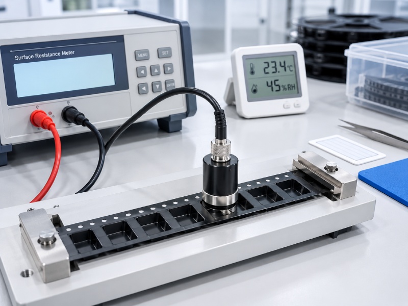
Humidity can affect the resistance of certain antistatic materials and surface treatments.
For packaging material product qualification under IEC 61340-5-3:2022, the specified conditions include:
-
Temperature: 23 ± 2°C
-
Relative Humidity: 12 ± 3% RH
-
Preconditioning: At least 48 hours
Routine inspections may use different conditions according to the approved test procedure. Always record the actual temperature and humidity.
Test Voltage and Measurement Time
Test voltage and reading time can influence resistance measurements. Use the settings required by the selected test method and ensure the instrument is suitable for the expected resistance range.
Record these settings to support consistent comparisons.
Electrode Contact and Sample Positioning
Embossed carrier tape has narrow flanges and formed pockets that can make electrode contact difficult.
Ensure that the electrode contacts the intended surface, the specimen remains stable, and the supporting fixture does not affect the measurement. Avoid deforming the tape during testing.
Sample Surface Condition
Dust, fingerprints, oils, and surface damage may affect test results.
Inspect samples before measurement and follow the specified handling and conditioning procedure.
Consistent measurement conditions and complete test records are essential for reliable ESD carrier tape resistance evaluation.
4. Where Should Resistance Be Measured on Embossed Carrier Tape?
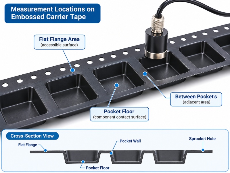
Unlike flat plastic film, embossed carrier tape contains pockets, flanges, sprocket holes, and formed surfaces. These features make electrode placement more difficult and can affect measurement repeatability.
The appropriate measurement location depends on the electrical property being evaluated and the applicable test procedure.
Flat Film Before Embossing vs. Finished Carrier Tape
Testing flat material before embossing can help verify the electrical characteristics of the incoming plastic sheet.
However, the finished carrier tape may have different surface characteristics after thermoforming.
During forming, the material is stretched into cavities. Thickness distribution and surface geometry change, and some coatings or conductive networks may be affected.
These changes do not necessarily indicate a defect, but they explain why raw-material measurements cannot always replace finished-product evaluation.
When an application requires electrical performance at the component-contact surface, measurements should represent that surface as closely as the applicable method permits.
Measuring Pocket Surfaces and Adjacent Areas
Depending on the test objective, engineers may need to evaluate several areas:
-
Pocket floor: The surface supporting the packaged component.
-
Flat flange: An accessible area that may accommodate an electrode.
-
Adjacent cavities: Locations relevant to cavity-to-cavity resistance measurements.
-
Cavity-to-reference arrangement: A configuration used when evaluating a specified resistance path involving a reference plate.
IEC 61340-5-3 includes carrier-tape-specific measurement guidance, while IEC TR 61340-5-5 addresses the limitations encountered with small packaging structures.
The measurement location must match the property being evaluated. A reading taken on an accessible flange should not be presented as a pocket-floor result.
For very small cavities, the specified electrode may not fit properly. In that case, the test laboratory and customer should agree on a technically justified alternative procedure.
Carrier tape width, pocket pitch, and cavity dimensions may help identify suitable measurement areas, but they are not themselves electrical performance requirements.
5. Step-by-Step Surface Resistance Testing Procedure
For embossed carrier tape, the testing procedure should account for narrow surfaces, formed pockets, and electrode contact limitations.
Step 1 — Select Measurement Locations
Identify the required test areas, such as the flat flange or pocket floor. Ensure each location is suitable for the selected electrode and measurement method.
Step 2 — Position the Sample and Electrode
Place the tape on the specified support and position the electrode carefully. Avoid bending the tape, crushing pockets, or contacting unintended surfaces.
Step 3 — Take and Record Readings
Apply the specified voltage and measurement time. Record individual resistance readings at the designated locations, including any unstable or out-of-range results.
Step 4 — Evaluate the Results
Compare the readings with the applicable acceptance criteria. If results are inconsistent, check electrode contact and measurement conditions before investigating potential material defects.
Consistent measurement locations and electrode positioning are essential for comparing resistance results across carrier tape samples.
6. Why Do Surface Resistance Readings Vary?
Surface resistance readings may differ even within the same batch of ESD carrier tape. However, these differences do not necessarily indicate inconsistent material quality.
For embossed carrier tape, measurement geometry is a major factor. A flat flange and a recessed pocket have different contact surfaces, making their readings difficult to compare directly.
The pattern of variation can help identify the problem:
-
Unstable readings at one location may indicate inconsistent electrode contact or measurement limitations.
-
Differences between tape locations may reflect surface geometry or actual material variation.
-
Differences between production batches may require further evaluation of material consistency and manufacturing conditions.
Before drawing conclusions, engineers should confirm that the measurement method is suitable and the results are repeatable.
Only comparable, valid measurements should be used to assess variations in carrier tape electrical performance.
7. How to Interpret and Report Surface Resistance Results
Surface resistance results should be evaluated against the specified acceptance limits using the applicable test method. A reading within the required range may indicate compliance, but only if the measurement is valid.
For ESD carrier tape, the inspection report should include:
-
Sample Information: Material type, part number, and production lot.
-
Test Details: Measurement method, electrode configuration, and test location.
-
Test Conditions: Temperature, humidity, test voltage, and measurement time.
-
Results: Individual resistance readings, units, and acceptance limits.
Results outside the instrument‘s measurement range should be identified accordingly rather than assigned an unsupported numerical value.
If a valid reading falls outside the specified limits, the material should be reviewed according to the approved quality procedure before release.
Clear reporting allows manufacturers and customers to verify ESD carrier tape performance against agreed specifications.
8. Is Surface Resistance Testing Enough to Qualify ESD Carrier Tape?
Surface resistance testing is an important part of ESD carrier tape evaluation, but it cannot confirm all aspects of electrostatic protection.
Depending on the component‘s sensitivity and packaging requirements, additional evaluations may include:
-
Low-Charging Performance: Assess electrostatic charge generation during tape movement and cover tape peeling.
-
Packaging Compatibility: Check pocket fit, cover tape sealing, peel force, and component handling during SMT feeding.
-
ESD Protection Requirements: Evaluate other relevant electrical properties, including discharge shielding where applicable.
A carrier tape that meets its surface resistance specification may still require additional testing under actual packaging and handling conditions.
Complete qualification should consider both the required electrical properties and the performance of the finished tape-and-reel packaging system.
9. Frequently Asked Questions
Can a Flat-Sheet Resistance Report Be Used to Approve Finished Embossed Carrier Tape?
Flat-sheet resistance data can support material qualification, but it may not fully represent the electrical properties of finished embossed carrier tape.
Forming changes the specimen geometry and may affect surface characteristics. If the approved qualification plan requires measurements on the finished tape, flat-sheet results alone may be insufficient.
When direct measurement is impractical, the applicable standard and an agreed alternative evaluation procedure should guide the decision.
Does Black Carrier Tape Automatically Have Conductive or ESD-Safe Properties?
No. The color of carrier tape does not establish its electrical characteristics.
Black carrier tape may contain conductive additives, but appearance alone cannot confirm the material‘s resistance classification or low-charging behavior.
Likewise, transparent or differently colored materials may be formulated for electrostatic-control applications.
The appropriate evaluation depends on the material specification and verified electrical test results.
Should Surface Resistance Be Rechecked After a Material or Tooling Change?
A material or tooling change should trigger an engineering assessment to determine whether electrical requalification is necessary.
Changes involving resin formulation, conductive additives, coatings, forming conditions, or component-contact surfaces may affect the finished tape.
The extent of retesting should follow the approved change-control process rather than assuming that every adjustment requires identical qualification testing.
Can Surface Resistance Measurements Predict Component Sticking During Cover Tape Peeling?
Not reliably on their own.
Component sticking can involve electrostatic charge generation, attraction, surface interaction, component geometry, and mechanical handling conditions.
A carrier tape may meet its specified resistance requirement while still exhibiting undesirable behavior during cover tape removal.
Investigation may require charge-related testing and observation of the actual tape-and-reel process.
What Should Buyers Request When Supplier and Incoming-Inspection Results Do Not Agree?
Buyers should request the complete test method, instrument and electrode information, measurement locations, conditioning history, test voltage, measurement time, and individual results.
Both parties should also confirm that they are evaluating the same electrical property and acceptance criteria.
Where necessary, representative samples should be retested under an agreed procedure before making a final material acceptance decision.
10. Engineering Review and Sample Approval
Reliable ESD carrier tape surface resistance testing requires more than a resistance meter and a numerical specification.
The test method must be suitable for the specimen geometry, environmental conditions must be controlled, electrode contact must be reproducible, and the results must be evaluated against clearly defined requirements.
For finished embossed carrier tape, particular attention should be given to measurement locations and the limitations of conventional electrodes.
Before approving a material for production, engineering and quality teams should agree on the electrical property, test method, acceptance criteria, and inspection records required for the intended application.
When evaluating ESD embossed carrier tape, providing the component drawing, material specification, required electrical properties, and testing requirements helps establish a more meaningful technical review.
For other material configurations, the existing carrier tape product range provides a starting point for reviewing packaging designs and material options.
The objective is not simply to obtain a resistance reading within a specified range. It is to establish a reproducible test process that supports consistent material qualification, reliable inspection, and appropriate electrostatic protection during electronic component packaging.



 Emial
 John Mr