






Leader & Trailer Tape Failures: SMT Feeder Checklist
Leader and trailer tape failures can interrupt SMT production before the first component is picked or when a reel is nearly empty. Common symptoms include carrier tape jamming during loading, irregular indexing, cover tape tearing, and feeder stoppages before the final components reach the pickup position.
The first inspection should focus on leader and trailer length, empty-pocket condition, sprocket holes, cover tape sealing, and reel-hub attachment. However, these symptoms do not always indicate defective packaging. Incorrect feeder settings, improper threading, and mechanical resistance can produce similar problems.
This guide explains how to inspect leader and trailer tape, identify likely failure causes, distinguish packaging defects from feeder issues, and document findings for engineering review.
1. Where Do Leader and Trailer Tape Failures Occur in an SMT Feeder?
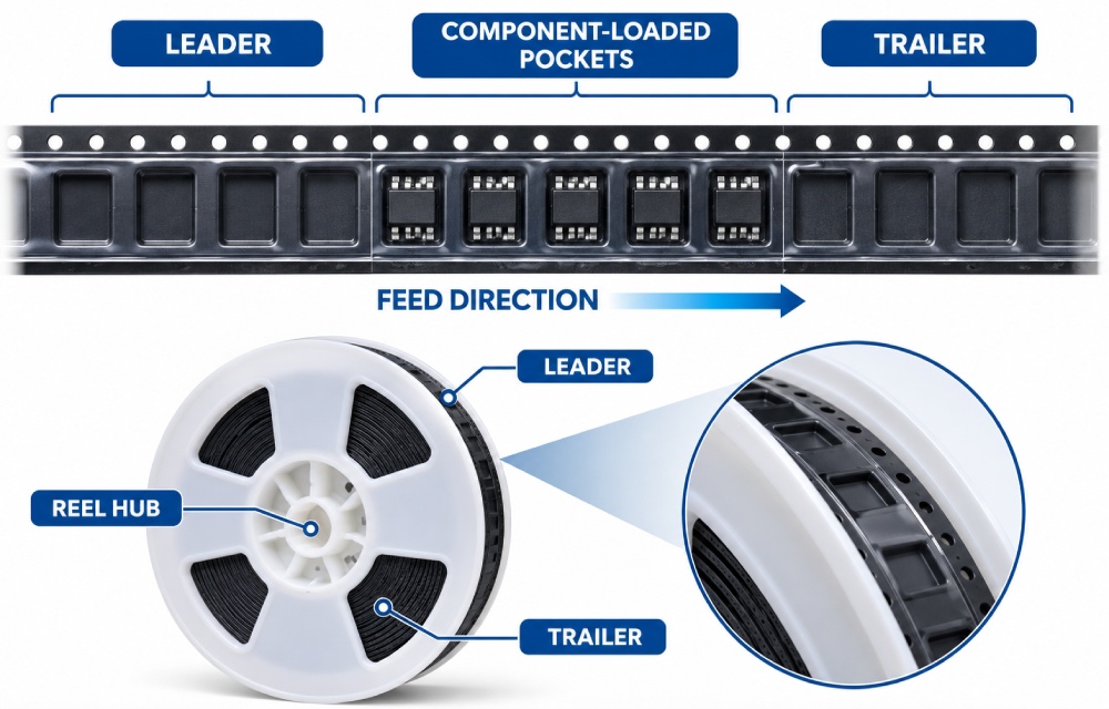
In tape-and-reel packaging, the leader and trailer are component-free sections located at opposite ends of the carrier tape. Both support reliable feeding, but they serve different purposes.
Leader Tape at the Start of a Reel
The leader is located at the outer end of the wound reel. It provides the material needed to thread the carrier tape through the feeder and establish the cover tape peeling path before component pickup begins.
Depending on the applicable packaging specification, the leader may include empty carrier tape pockets sealed with cover tape and a separate cover-tape extension.
A leader problem usually appears during:
-
Initial carrier tape insertion
-
Sprocket engagement and indexing
-
Cover tape threading or take-up
-
Transition to the first component-loaded pocket
An insufficient or damaged leader can make loading difficult even when the component-loaded section meets dimensional requirements.
Trailer Tape Near the Reel Hub
The trailer is the empty section between the last component-loaded pocket and the inner end of the carrier tape near the reel hub.
Its purpose is to allow the final loaded pockets to travel through the feeder before the remaining carrier tape reaches the end of the reel.
Trailer-related failures may occur when:
-
The remaining empty tape is insufficient for the feeder‘s operating sequence.
-
The carrier tape becomes difficult to unwind near the hub.
-
Excessive attachment resistance interferes with the final advances.
-
The feeder reaches an end-of-tape condition earlier than expected.
The key distinction is the failure location: leader problems usually affect startup, while trailer problems usually affect reel completion.
2. What Should Be Checked Before Loading a Component Reel?
A pre-loading inspection helps identify packaging defects before they become feeder interruptions. The inspection should cover tape length, physical condition, sealing, and reel compatibility.
Leader and Trailer Length Verification
Leader and trailer length should be checked against the approved packaging drawing and the applicable customer or component-manufacturer specification.
For reference, onsemi‘s October 2026 Tape & Reel Packaging Standards specify a minimum leader length of 400 mm and a minimum trailer length of 160 mm for the configurations described in that document. Both sections contain empty cavities with sealed cover tape.
These published manufacturer requirements should not automatically replace the acceptance criteria for a different component or packaging configuration.
During inspection:
-
Identify the first and last component-loaded pockets.
-
Establish the measurement reference points specified in the applicable drawing.
-
Measure the leader from its defined starting point to the first loaded-pocket boundary.
-
Measure the trailer from the last loaded-pocket boundary to the defined inner tape end.
-
Record any separate cover-tape-only extension where applicable.
-
Compare the measurements with the approved requirements.
Partially consumed reels and previously trimmed reels need particular attention because their original leader or trailer configuration may have changed.
Sprocket Holes and Tape Edge Condition
Sprocket holes must engage consistently with the feeder drive mechanism.
Inspect the leader and trailer for torn holes, elongated openings, distorted edges, localized bending, and damage near tape transitions.
Also check whether the tape width and hole arrangement match the intended feeder configuration.
A short section of damaged sprocket holes may be enough to interrupt indexing even when the rest of the reel appears normal.
Cover Tape Sealing and Reel Condition
Cover tape should remain correctly positioned over the carrier tape and separate predictably during the approved feeding process.
Before loading, inspect for wrinkles, loose ends, damaged sealing areas, and unexpected changes in cover tape alignment.
The reel should also be checked for damaged flanges, displaced tape layers, and visible obstruction around the hub.
Any abnormal condition should be documented before trimming or reworking the tape.
3. Why Does Leader Tape Fail During SMT Feeder Loading?
Leader tape failures often become visible before the first component reaches the pickup position. The failure may involve the tape itself, the cover tape path, or the interaction between the carrier tape and feeder mechanism.
Insufficient or Damaged Leader Length
A leader that is too short for the required loading procedure may not provide enough material to establish the carrier tape and cover tape paths.
Operators may experience difficulty reaching the take-up mechanism or positioning the first loaded pocket without exposing components prematurely.
Damage can also occur when a leader is repeatedly folded, pulled, or trimmed during handling.
Inspect the usable length rather than relying only on the original reel label. Record whether the reel has already been opened or partially consumed.
Sprocket Engagement and Initial Indexing Failure
The feeder advances carrier tape through engagement between its drive mechanism and the tape‘s sprocket holes.
If the leader enters the guide incorrectly, the holes may not engage properly. Torn holes, local deformation, and an incorrectly selected feeder can produce similar symptoms.
When irregular advancement occurs, inspect:
-
Sprocket-hole condition near the tape entry point
-
Tape alignment within the guide
-
Compatibility between tape width and feeder
-
Programmed component pitch or mechanical advance settings
-
Feeder drive and guide condition
A tape that indexes correctly on a compatible feeder but repeatedly fails on another may require equipment investigation rather than immediate packaging rejection.
Cover Tape Peeling Problems During Threading
Cover tape tearing or slipping during initial loading may result from incorrect routing, twisting, inadequate engagement with the take-up mechanism, or abnormal seal behavior.
For example, a cover tape that is routed incorrectly around a peeling guide may experience localized tension. The resulting tear can resemble a material defect.
Inspect the separation point and confirm that the cover tape follows the machine manufacturer‘s specified path.
Where material or sealing compatibility is suspected, review the cover tape used in carrier tape packaging and the approved sealing requirements.
Failure at the First Component-Loaded Pocket
Some reels feed normally through the empty leader but encounter problems when the first loaded pocket reaches the pickup area.
This transition may reveal a previously unnoticed change in cover tape behavior, pocket geometry, or component positioning.
The inspection should identify whether the problem occurs immediately before, during, or after exposure of the first component.
The first loaded pocket should be examined for deformation, abnormal component orientation, or cover tape interference.
Common Leader Tape Failure Symptoms
| Observed symptom | Possible cause | Initial inspection |
|---|---|---|
| Leader cannot reach the required threading path | Insufficient usable length | Measure leader and verify loading requirements |
| Tape advances irregularly | Poor sprocket engagement or damaged holes | Inspect holes, alignment, and feeder settings |
| Cover tape tears during loading | Incorrect routing or abnormal sealing | Check peel path and seal condition |
| Tape becomes folded at entry | Tape deformation or guide interference | Inspect edges and feeder guide |
| First loaded pocket fails to advance correctly | Transition damage or indexing issue | Inspect transition and pickup position |
The table identifies investigation priorities, not confirmed root causes. Each suspected condition must be verified before corrective action is selected.
4. What Causes Trailer Tape Failures at the End of a Reel?
Trailer failures occur during the final stages of component feeding, when the remaining carrier tape approaches the reel hub.
Unlike leader problems, these failures may appear after a long period of otherwise stable operation.
Insufficient Empty Trailer Tape
The trailer provides empty carrier tape after the final loaded pocket. This allows the feeder to complete the last component-feeding operations without immediately reaching the physical end of the tape.
When the trailer is insufficient, the feeder may lose reliable tape engagement before all components have reached their intended pickup positions.
However, an early feeder stop can also result from incorrect remaining-component counts or end-of-tape detection settings.
Engineers should compare the physical tape position, actual remaining components, and the machine‘s operating records before concluding that the trailer is defective.
Reel Hub Attachment and Tape Release Problems
The inner end of the carrier tape must be secured appropriately during packaging while allowing release in accordance with the applicable reel specification.
Problems may occur when attachment materials, fixing tape, or the reel-hub configuration create abnormal resistance during final unwinding.
Typical signs include sudden tape tension, restricted reel rotation, and tape deformation near the hub.
Inspect the attachment method and determine whether the tape can release as intended without disturbing the final loaded pockets.
The attachment should not be modified during troubleshooting unless an approved procedure permits it.
Reel Drag and Winding-Related Resistance
As a reel approaches completion, changes in the remaining winding diameter and tape path may expose mechanical resistance that was not apparent earlier.
Potential contributing conditions include:
-
Flange interference with the tape
-
Displaced or uneven tape layers
-
Localized carrier tape deformation
-
Excessive resistance near the hub
-
Feeder take-up or guide problems
When resistance is observed, inspect both the plastic reel and the feeder mechanism.
The point at which resistance begins is important evidence. A problem limited to the final winding layers suggests a different investigation from a problem occurring throughout the entire reel.
5. Leader and Trailer Tape Inspection Checklist for SMT Feeders
A structured inspection checklist allows operators and quality engineers to identify abnormalities consistently.
The checklist below covers three stages: before loading, during initial feeding, and near reel completion.
Before Loading — Leader Inspection
Start by comparing the received reel with its packaging specification.
Check whether the leader provides the required usable length and whether the empty-pocket section is intact.
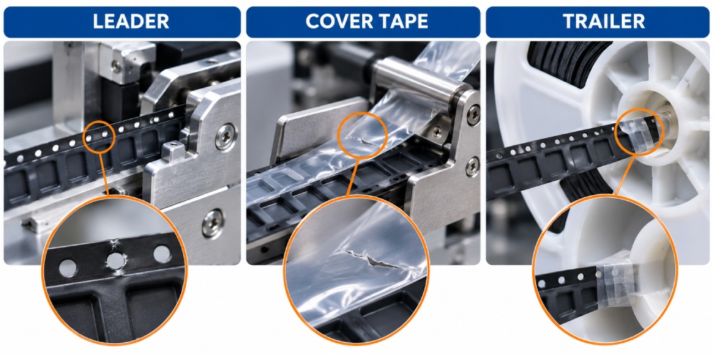
Inspect sprocket holes, tape edges, cover tape alignment, and visible reel condition. Photograph any abnormalities before handling changes the evidence.
During Initial Feeding — Functional Checks
Verify feeder compatibility and observe the initial tape advance using the equipment manufacturer‘s approved loading procedure.
Check the sprocket engagement, cover tape routing, and transition toward the first component-loaded pocket.
A normal initial advance does not necessarily confirm that the first loaded-pocket transition will function correctly.
Near Reel Completion — Trailer Inspection
When investigating a previous end-of-reel failure, preserve the affected reel and determine the location of the final loaded pocket.
Inspect the remaining trailer, reel-hub attachment, and any evidence of restricted unwinding.
For production equipment, use approved maintenance or engineering procedures rather than manually interfering with moving feeder parts.
12-Point Leader and Trailer Tape Inspection Checklist
| Stage | Inspection item | Method | Evidence to record |
|---|---|---|---|
| Before loading | 1. Leader length | Measure against approved drawing | Actual length |
| Before loading | 2. Empty-pocket section | Visual examination | Pocket condition |
| Before loading | 3. Sprocket holes | Visual or magnified inspection | Hole damage and location |
| Before loading | 4. Cover tape seal | Inspect alignment and continuity | Seal condition |
| Before loading | 5. Reel condition | Inspect flange and winding | Visible abnormalities |
| Initial feeding | 6. Feeder compatibility | Check tape width and feeder specification | Feeder model |
| Initial feeding | 7. Sprocket engagement | Observe approved indexing operation | Advance behavior |
| Initial feeding | 8. Cover tape routing | Inspect the peeling and take-up path | Routing condition |
| Initial feeding | 9. First loaded-pocket transition | Observe initial component exposure | Failure position |
| Near completion | 10. Final loaded pockets | Inspect remaining component section | Pocket count and condition |
| Near completion | 11. Trailer length | Measure against approved drawing | Actual length |
| Near completion | 12. Hub release and final advance | Inspect or conduct approved functional verification | Resistance or alarm record |
How to Record Inspection Results
Each item should receive one of three classifications:
Pass: The inspected condition meets the applicable documented acceptance requirement.
Hold: A defect, mismatch, or unresolved observation requires engineering or quality review.
Not Applicable: The feature or inspection does not apply to the specific packaging configuration.
A Hold result should not be converted to Pass merely because the feeder operates successfully during a brief trial.
Where a defect may affect component retention, pocket alignment, or feeding reliability, the responsible quality or engineering team should determine the appropriate disposition.
6. How Can You Distinguish Tape Packaging Failures From SMT Feeder Problems?
When an SMT feeder stops during reel loading or near the end of a reel, the cause may involve the carrier tape, cover tape, reel, or feeder mechanism. The most effective approach is to identify where the failure occurs and compare the affected reel with a known-good setup.
Check the Failure Location
The position of the tape when the problem occurs provides useful clues:
-
During initial loading: Check leader length, sprocket-hole condition, and tape alignment.
-
At the first loaded pocket: Inspect cover tape separation, pocket condition, and feeder indexing.
-
During normal feeding: Check tape deformation, sprocket engagement, and feeder settings.
-
Near the reel end: Inspect trailer length, reel-hub attachment, and remaining tape movement.
Compare the Reel and Feeder
First, inspect the suspected reel for visible damage and dimensional differences from the approved packaging specification.
Next, where the equipment procedure permits, test a compatible known-good reel on the same feeder. If the same problem occurs, check the feeder guides, sprocket drive, cover tape path, and indexing settings.
If the suspected reel repeatedly fails on different qualified feeders while comparable reels operate normally, investigate the packaging condition more closely.
Confirm the Root Cause
Record the failure position, feeder model, reel identification, and inspection findings. Keep other operating conditions consistent during comparison tests.
Do not classify the issue as a packaging defect or feeder malfunction based on a single alarm. Corrective action should follow the inspection evidence and engineering review.
7. What Measurements and Evidence Should Be Included in an Inspection Report?
An inspection report should allow another engineer to understand the failure, identify the affected material, and reproduce the relevant observations where practical.
Descriptions such as "tape jammed" or "cover tape too tight" are insufficient without supporting evidence.
Dimensional and Visual Evidence
Record the leader or trailer length using clearly defined measurement reference points.
If sprocket-hole damage is present, identify its position relative to the first or last component-loaded pocket.
Photographs should show both the complete affected area and a close-up of the defect.
Useful observations include tape-edge damage, cover tape separation, pocket deformation, and unusual hub attachment conditions.
Peel and Feeder Operating Evidence
If cover tape behavior is suspected, record whether the tape tears, separates unevenly, slips within the take-up mechanism, or requires abnormal force.
Quantitative peel-force evaluation should use a documented test method with the specified angle, speed, sample preparation, and acceptance requirements.
Visual observation alone cannot establish whether the measured peel force is outside specification.
For additional technical background, see Carrier Tape Peel Force Explained for Stable SMT Assembly.
Feeder records should identify the equipment model, relevant settings, alarm description, and operating stage.
Engineering Inspection Record
| Information | Required record |
|---|---|
| Component identification | Part number and packaging specification |
| Material traceability | Reel identification and batch or lot number |
| Equipment | Feeder model and identification |
| Failure stage | Initial loading, first pocket, normal feeding, or reel completion |
| Dimensional inspection | Measured leader/trailer length and reference requirement |
| Visual findings | Photographs and defect descriptions |
| Functional comparison | Results from approved reel or feeder comparisons |
| Preliminary conclusion | Packaging-related, feeder-related, or unresolved |
| Review status | Responsible engineer and disposition decision |
The report should distinguish confirmed findings from suspected causes. This prevents corrective actions from being based only on operator assumptions.
8. What Corrective Actions Can Prevent Repeated Leader and Trailer Failures?
Corrective action should address the verified cause rather than simply allowing the affected reel to pass through the feeder.
Packaging-Related Corrective Actions
For confirmed packaging defects, review the corresponding manufacturing or inspection controls.
Possible actions include:
-
Correcting leader or trailer length against the approved drawing
-
Reviewing sprocket-hole damage and tape-edge handling
-
Investigating cover tape sealing and material compatibility
-
Checking winding conditions and reel-hub attachment procedures
-
Improving inspection of the first and last component-loaded sections
Changes to tape materials, sealing methods, splicing practices, or reel attachment should be evaluated before implementation.
Unapproved trimming or splicing may introduce additional feeding problems.
Feeder-Related Corrective Actions
When the investigation identifies an equipment issue, verify the feeder configuration and maintenance condition.
Review tape width compatibility, indexing settings, sprocket engagement, cover tape routing, and relevant detection functions.
Any mechanical adjustment or repair should follow the equipment manufacturer‘s instructions.
Feeder settings should not be changed simply to compensate for a known packaging nonconformity.
Sample Verification and Production Release
After corrective action, inspect representative samples against the approved requirements.
Where relevant, conduct controlled feeder verification covering initial loading, the first component-loaded pocket, normal feeding, and the final loaded pockets.
Record whether the original failure condition has been eliminated.
Production release should depend on documented inspection and verification results, with approval by the responsible engineering or quality personnel.
9. Frequently Asked Questions
Can unembossed carrier tape be used as leader or trailer tape?
Unembossed carrier tape may be considered for certain packaging configurations if dimensional compatibility and feeder operation are validated.
ECIA‘s technical knowledge document discusses this approach but does not endorse splicing. In particular, sprocket-hole alignment and spacing must remain suitable for the applicable packaging requirements.
Any alternative construction requires appropriate technical review and approval.
Is it acceptable to splice additional leader tape onto a short reel?
Adding a leader by splicing is not automatically acceptable.
A splice may introduce local thickness variation, sprocket-hole misalignment, or interference with the feeder and cover tape path.
Rework should only proceed under a validated procedure approved by the relevant packaging and assembly engineering teams.
Why does the same reel work on one SMT feeder but fail on another?
Different feeders may have different guide geometries, cover tape routing systems, indexing mechanisms, and setup requirements.
Equipment condition and configuration can also influence feeding behavior.
Compare the reel on qualified feeders under controlled conditions before assigning the root cause to the tape or equipment.
What should be retained after an intermittent end-of-reel failure?
Retain the affected reel and remaining tape section whenever practical.
Also preserve photographs, feeder identification, alarm records, relevant measurements, and the locations of the last loaded pockets.
Avoid unnecessary trimming or rework before the affected material has been documented.
10. Conclusion: Verify Leader and Trailer Conditions Before Reel Release
Leader and trailer tape failures require different inspection priorities. Initial loading problems should focus on leader length, threading, sprocket engagement, and cover tape separation. End-of-reel failures require additional attention to trailer length, final component feeding, and reel-hub release.
A structured inspection checklist, supported by dimensional measurements and controlled feeder comparisons, helps engineers distinguish packaging defects from equipment-related problems.
When abnormalities involve cover tape compatibility, carrier tape geometry, or plastic reel performance, review the approved packaging specifications before corrective action and production release.



 Emial
 John Mr