








Carrier Tape Specifications & EIA-481 Standard Explained for SMT Packaging
Why Carrier Tape Specifications Matter in SMT Packaging
In SMT packaging, carrier tape specifications are not just a checklist to pass inspection—they define how the entire tape & reel system behaves in real production. A carrier tape does not work in isolation; it functions as an integral part of the feeder mechanism, interacting continuously with sprockets, indexing systems, and pick-and-place nozzles.
From an engineering perspective, specifications describe relationships, not individual dimensions. Pitch, pocket position, hole alignment, and tolerance together determine whether components advance smoothly, stop accurately, and remain stable at speed. When these relationships are misunderstood, problems often appear as “random” feeder errors or yield loss, even though the tape seems compliant on paper.
This is why many SMT issues are not caused by obvious non-compliance, but by partial or superficial understanding of specifications. Treating carrier tape specs as a system language—rather than a formality—is essential for feeder compatibility, process stability, and long-term yield control.
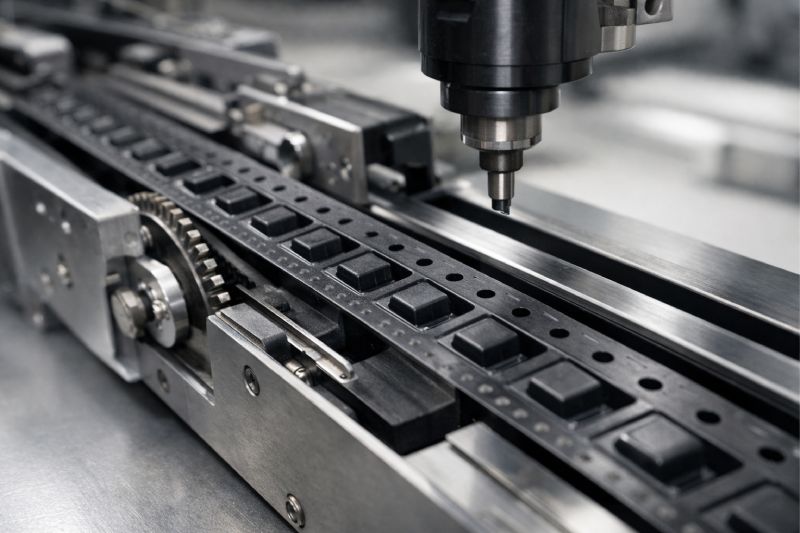
What Are Carrier Tape Specifications?
From an engineering standpoint, carrier tape specifications define how a tape is expected to function within a tape & reel and feeder system, not just how it looks when measured. They describe a coordinated set of parameters that allow components to be transported, indexed, and presented consistently during SMT assembly.
These specifications typically cover overall dimensions, pocket geometry, pitch, sprocket hole position, and allowable variation. Individually, each item may seem straightforward. In practice, their value lies in how they work together to maintain timing accuracy, positional repeatability, and mechanical stability throughout the feeding process.
Rather than acting as isolated rules, carrier tape specifications form a shared reference between tape design, manufacturing, and equipment operation. They ensure that tapes produced by different suppliers can run on standard feeders, and that feeders can operate predictably across different component types.
Understanding specifications this way helps engineers avoid treating them as static requirements—and instead use them as tools for reliable system integration.
Overview of the EIA-481 Standard
The EIA-481 standard exists to solve a very practical problem in SMT packaging: how to ensure that carrier tapes, cover tapes, reels, and feeders from different sources can work together reliably. Rather than optimizing for any single machine or component, the standard establishes a common engineering baseline for compatibility and interchangeability across the tape & reel ecosystem.
At its core, EIA-481 defines how carrier tape features—such as tape width, pocket layout, sprocket hole positioning, and allowable variation—should relate to one another so that feeders can index consistently and place components accurately. This consistency is what allows SMT lines to switch between suppliers, components, or tape designs without re-engineering the entire feeding system.
Importantly, the standard is not a performance guarantee. It does not claim that every EIA-481–compliant tape will run flawlessly under all production conditions. Instead, it provides a shared reference framework that reduces uncertainty and establishes minimum functional expectations.
EIA-481 is most applicable to embossed carrier tapes used in automated SMT assembly, particularly where standardized feeders and high-volume production are involved. By defining a common language rather than prescribing exact use cases, the standard enables scalable manufacturing while leaving room for engineering judgment in real-world applications.
Key Specification Elements in EIA-481
EIA-481 organizes carrier tape specifications into functional elements that directly correspond to how feeders locate, advance, and present components. Rather than focusing on individual numbers, the standard defines how these elements interact to support stable, repeatable feeding under automated conditions.
Tape Width & Overall Dimensions
Tape width and overall dimensions establish the physical interface between the carrier tape and the feeder track. When this relationship is well controlled, the tape is guided smoothly without lateral play or binding. If misunderstood or poorly matched, even a nominally compliant tape may tilt, wander, or introduce positional drift—issues that often appear only at production speed or after long run times.
Pitch & Pocket Position
Pitch and pocket position govern indexing accuracy. Each advance of the feeder relies on predictable spacing to stop components at the correct pick location. When pitch relationships are inconsistent, errors tend to accumulate rather than appear immediately, leading to mis-picks or placement offsets that are difficult to trace back to a single cause.
Sprocket Holes (D1 Hole)
Sprocket holes act as the primary mechanical reference for feeder drive and positioning. Their role is not merely to pull the tape forward, but to synchronize motion with pocket alignment. Small deviations in hole position or consistency can amplify through the feeder mechanism, resulting in unstable feeding even when other dimensions appear correct.
Together, these elements illustrate how EIA-481 defines functional relationships—where reliability depends on coordination, not isolated measurements.
Tolerance Considerations in Carrier Tape Specifications
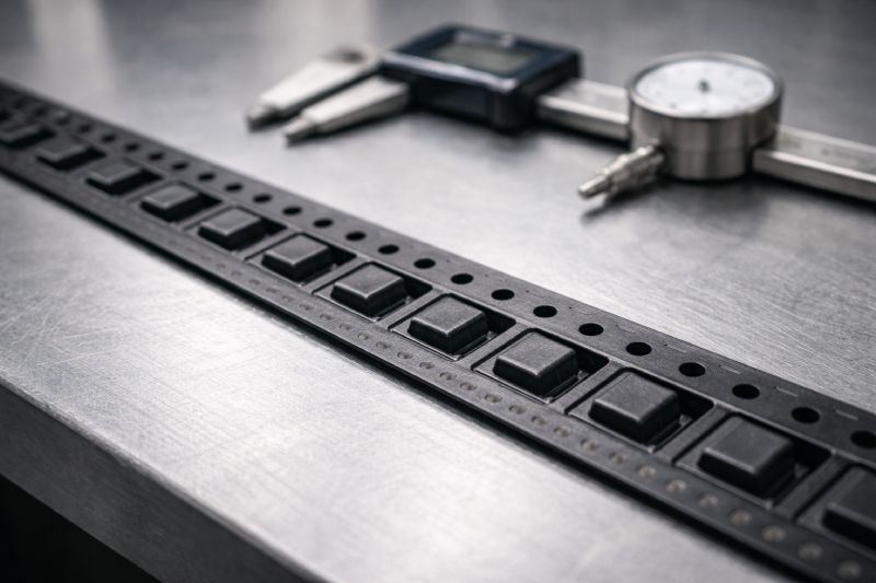
Tolerance is often where the gap between “theoretical compliance” and real feeder performance becomes visible. In carrier tape specifications, nominal dimensions describe intent—but it is tolerance that determines whether that intent survives actual production and operation.
In an SMT feeder, small variations do not remain isolated. Dimensional deviations in pitch, hole position, or pocket alignment accumulate as the tape advances, especially over long indexing cycles or high-speed operation. What appears insignificant in a single measurement can translate into timing drift, unstable stopping positions, or inconsistent component presentation downstream.
This is why tapes that technically conform to EIA-481 may still cause feeding issues. The standard defines acceptable ranges, but it does not account for how multiple tolerances interact simultaneously within a specific feeder design or process condition. Feeder mechanics, tape stiffness, cover tape interaction, and component mass all influence how tolerance is amplified or dampened.
From an engineering standpoint, tolerance should be evaluated as a system behavior, not a pass/fail criterion. Understanding how variation propagates through the feeder is essential for diagnosing problems and preventing the common situation where a tape is “within spec” but functionally unreliable.
Common Misunderstandings About EIA-481
One of the most common misconceptions about EIA-481 is the belief that compliance automatically guarantees trouble-free feeding. In reality, the standard defines a baseline for compatibility, not a promise of optimal performance under all conditions. Feeder behavior is influenced by many interacting factors that extend beyond what any single standard can capture.
Another frequent misunderstanding is equating “standard size” with “best design.” EIA-481 dimensions are meant to accommodate a wide range of components and equipment, which means they represent compromise solutions rather than optimized ones. For certain components or process speeds, strictly following standard dimensions may introduce unnecessary risk instead of reducing it.
There is also a belief that EIA-481 restricts customization. In practice, the opposite is true. The standard provides a common reference point that makes customization possible in a controlled and predictable way. Engineers can deviate from standard assumptions when needed—so long as they understand which relationships are critical to feeder function.
Recognizing these misconceptions helps shift EIA-481 from a rigid rulebook to what it truly is: an engineering foundation, not a design ceiling.
EIA-481 vs Real-World Carrier Tape Manufacturing
EIA-481 plays a critical role in guiding carrier tape manufacturing, but it does not replace engineering judgment on the production floor. The standard defines what relationships must exist; manufacturing determines how consistently those relationships can be achieved at scale.
In real-world production, material behavior, forming methods, and process control all influence how closely a finished tape matches its intended specification. Factors such as material shrinkage, tool wear, and forming stability can introduce variation that remains invisible in isolated checks but becomes evident during long feeder runs.
This is where manufacturing experience matters more than simply following a specification table. Skilled manufacturers understand which parameters are most sensitive in downstream feeding, and they adjust tooling, inspection methods, and process limits accordingly. Without this context, two tapes that look identical on paper may perform very differently in the same SMT line.
EIA-481 provides the framework, but reliable carrier tape manufacturing depends on translating that framework into repeatable, controlled processes—something no standard can define in full detail.
When Standard Carrier Tape Specifications Are Not Enough
While EIA-481 covers the majority of common SMT packaging scenarios, there are many situations where standard carrier tape specifications alone do not provide sufficient process stability. These cases typically emerge when component behavior or production requirements push beyond the assumptions built into the standard.
Non-standard components—such as irregular geometries, asymmetric leads, or unusually lightweight parts—often interact with pockets and cover tape in ways that standard dimensions were never designed to manage. Similarly, high-speed SMT lines reduce the system’s tolerance for variation, exposing minor alignment or retention issues that would otherwise remain hidden.
Projects with strict yield targets or low defect tolerance also tend to outgrow purely standard solutions. In these environments, relying solely on baseline specifications increases risk, because there is little margin for accumulated deviation or feeder-specific behavior.
In such cases, specifications become a starting point rather than a solution. Custom pocket design, controlled dimensional relationships, and application-specific drawings are often required to achieve stable feeding.
How to Use Carrier Tape Specifications Correctly
Using carrier tape specifications correctly starts with treating them as a shared engineering language, not a final acceptance checklist. Specifications are most effective when they guide communication between design, manufacturing, and SMT operation—ensuring that all parties are aligned on how the tape is expected to behave in the feeder.
In early project stages, specifications should be used to frame design intent: how components are retained, how they advance, and how accurately they must present at the pick position. During manufacturing, they help define process controls and inspection priorities, focusing attention on relationships that matter most to feeding stability rather than on isolated measurements.
Equally important is knowing when specifications alone are no longer sufficient. If feeder performance is sensitive, speeds increase, or component geometry introduces uncertainty, that is a signal to move beyond baseline standards and evaluate custom design options.
Applied this way, carrier tape specifications become a tool for risk management and system optimization—supporting reliable SMT performance instead of merely confirming compliance.
Summary
EIA-481 gives SMT packaging a common engineering foundation, but its real value lies in how well it is understood and applied. Carrier tape specifications are not about memorizing dimensions—they describe functional relationships that determine feeder stability, compatibility, and yield. When treated as a system language rather than a checklist, specifications help engineers prevent issues that appear compliant on paper but fail in production. Mastery comes from understanding interaction, tolerance behavior, and real manufacturing limits.



 Emial
Emial John Mr


