








Cover Tape for Carrier Tape: Types, Compatibility & SMT Stability Guide
What Is Cover Tape for Carrier Tape
Cover tape for carrier tape is not a standalone material—it is a system-level component within tape & reel packaging. Together with the carrier tape, it forms a controlled containment and release mechanism designed specifically for automated SMT handling.
In a tape & reel system, the role of cover tape is often misunderstood as simply “sealing” components inside pockets. In practice, its real function is controlled retention and predictable release. The cover tape must hold components securely during transport, storage, and feeder indexing, while also releasing them consistently at the pick-up point without disrupting placement accuracy.
Because of this, cover tape is never selected independently. It must be engineered to work in direct compatibility with the carrier tape’s material, pocket geometry, and application conditions. A cover tape that performs well on one carrier tape may fail entirely on another.
For a broader system view, see Carrier Tape and Reel Packaging Explained and Tape and Reel Packaging for SMT Components.
Why Cover Tape Compatibility Matters
Cover tape compatibility is one of the most common root causes behind unstable SMT feeding—even when the carrier tape itself is correctly designed. When the cover tape is mismatched, problems rarely appear as a single clear failure. Instead, they show up as cumulative instability across the entire placement process.
An incompatible cover tape can lead to feeding irregularities, inconsistent peel behavior, or sudden component loss during indexing. In high-speed SMT lines, even minor variations in peel force or release timing can translate into missed picks, shifted components, or intermittent feeder stoppages. These issues are often misattributed to feeder hardware or pick-and-place settings, when the real cause lies in the tape system.
This is why “just using a similar cover tape” does not work in SMT environments. Cover tape performance is tightly coupled with carrier tape material, pocket geometry, and process conditions. A cover tape that seals adequately but releases unpredictably can be more damaging than one that fails outright.
At a system level, cover tape acts as a multiplier of SMT stability. When compatibility is correct, the line runs quietly. When it is not, small mismatches quickly become large process risks.
Types of Cover Tape Used with Carrier Tape
In SMT packaging, cover tape is not classified by brand or chemistry first, but by how it functions within the tape & reel system. From an engineering perspective, there are two dominant cover tape types used with carrier tape, each defined by its bonding and release behavior rather than its material formulation.
Heat-Activated Cover Tape
Heat-activated cover tape forms a bond with the carrier tape through controlled thermal sealing. During the sealing process, heat and pressure activate the adhesive layer, creating a consistent seal along the pocket edges.
This type is commonly used in high-volume, high-speed SMT applications where sealing consistency and long-term retention are critical. Because the seal is formed through a defined process window, heat-activated cover tape offers good repeatability when paired with a compatible carrier tape.
However, this also means the carrier tape must be designed to tolerate thermal input. Material stability, pocket edge geometry, and surface characteristics all influence seal quality. If the carrier tape is not engineered for heat sealing, peel force variability and partial sealing can occur.
Pressure-Sensitive Cover Tape
Pressure-sensitive cover tape relies on adhesive contact rather than thermal activation. Sealing occurs through applied pressure, without a heating step, making it suitable for applications where heat exposure must be minimized.
Compared to heat-activated types, pressure-sensitive cover tape is more sensitive to surface conditions and material compatibility. It is often used in lower-speed lines, prototyping stages, or applications where carrier tape materials do not support thermal sealing.
The key distinction is not performance hierarchy, but application boundary. Pressure-sensitive cover tape demands tighter control of carrier tape surface properties, while heat-activated cover tape demands tighter control of process conditions.
How Cover Tape Works with Carrier Tape
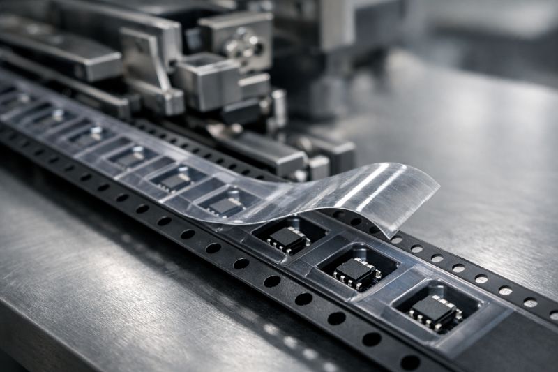
Cover tape does not function independently—it operates as part of a dynamic retention system formed together with the carrier tape. The effectiveness of this system depends on how the cover tape interacts with pocket geometry, component mass, and feeder motion throughout the SMT process.
At rest, the cover tape contributes to pocket retention by applying a controlled holding force that prevents components from lifting, rotating, or migrating during transport and indexing. This retention is not static. As the tape advances through the feeder, mechanical stress, acceleration, and vibration continuously act on the component. The cover tape must absorb these forces without losing positional stability.
During pick-up, peel force becomes the critical variable. If the peel force is too high, the component may shift, tilt, or resist vacuum pickup. If it is too low, premature release can occur before the pick head reaches the pocket. This is why peel behavior must be predictable rather than minimal.
Importantly, peel force is not a fixed material property. It changes with feeder speed, peel angle, sealing conditions, and carrier tape design. In this sense, cover tape is a dynamic parameter, not a static material choice.
This system interaction is closely tied to carrier tape structure. Pocket design principles are covered in Carrier Tape Design Guide, while indexing and spacing effects are addressed in Carrier Tape Pitch.
Cover Tape Compatibility with Carrier Tape Materials
Cover tape compatibility is fundamentally governed by the carrier tape material it seals onto. Even when pocket design and process settings are correct, an incompatible material pairing can destabilize peel behavior and retention performance.
PS (Polystyrene) carrier tape is widely used due to its formability and cost efficiency, but it is also the most sensitive to cover tape selection. PS surfaces react strongly to adhesive chemistry and sealing conditions. A cover tape that bonds too aggressively can cause excessive peel force, while insufficient interaction leads to lifting or incomplete sealing. This makes PS compatibility highly dependent on controlled pairing rather than generic cover tape use. See PS Carrier Tape for material-specific considerations.
PET carrier tape offers better dimensional stability and surface consistency. As a result, PET generally provides a wider compatibility window with both heat-activated and pressure-sensitive cover tapes. However, this does not eliminate risk. Surface energy differences and pocket edge finish still influence peel consistency, especially at higher SMT speeds. More details are covered in PET Carrier Tape.
PC (Polycarbonate) carrier tape introduces a different balance. Its rigidity and thermal resistance support stable heat sealing, but its surface characteristics require careful adhesive matching. Using an incompatible cover tape can result in uneven seal strength across the tape width. A comparative overview is discussed in PC vs PS Carrier Tape.
For conductive carrier tape, compatibility extends beyond mechanical behavior. Adhesive interaction must not compromise conductivity or introduce contamination risks. In these cases, cover tape selection becomes a functional as well as material decision, as outlined in Conductive Carrier Tape.
Common Cover Tape Compatibility Issues
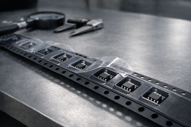
Most cover tape problems do not appear as immediate, catastrophic failures. Instead, they surface as process instability that becomes visible only after SMT lines reach speed or volume. These issues are almost always rooted in compatibility rather than installation error.
Excessive peel force is one of the most frequent symptoms. When the adhesive interaction between cover tape and carrier tape is too strong, peel force increases beyond what the component or pick-up process can tolerate. This can cause component movement at the moment of release, partial lifting, or vacuum pickup failure—even when sealing appears visually correct.
Inconsistent sealing is another common issue, particularly across different production lots or along the tape width. This typically occurs when the cover tape responds unevenly to carrier tape surface characteristics or thermal input. The result is variable retention from pocket to pocket, which undermines placement repeatability.
Cover tape lifting during transport often indicates insufficient compatibility under dynamic stress. While the tape may appear sealed after packaging, vibration, temperature changes, or feeder acceleration can cause localized lifting, exposing components before they reach the pick position.
Finally, component jumping or shifting usually points to unstable retention rather than pocket design alone. When cover tape release behavior is unpredictable, components may rebound or rotate during peel, creating downstream placement errors without an obvious single-point cause.
These issues rarely have a single “fix” because they originate at the system level—where cover tape, carrier tape, and process conditions intersect.
How to Select the Right Cover Tape for Your Carrier Tape
Selecting cover tape is not about choosing the “strongest” or “most common” option. It is a decision process driven by how the component, carrier tape, and SMT line interact as a system.
If the component is lightweight or low-profile, peel force behavior becomes the primary concern. In these cases, stable and repeatable release matters more than maximum retention strength. A cover tape that holds too aggressively can introduce more risk than benefit at pick-up.
If the SMT line operates at high placement speeds, release consistency takes priority. As feeder acceleration increases, small variations in peel behavior are amplified. Here, the goal is not minimum peel force, but controlled and uniform release across the entire reel.
Carrier tape material further narrows the decision. With PS carrier tape, compatibility must be verified carefully due to its sensitivity to adhesive interaction. PET carrier tape allows more flexibility but still requires attention to surface finish and sealing behavior. PC carrier tape favors stable heat-seal processes but demands precise adhesive matching to avoid uneven peel force.
Rather than selecting cover tape in isolation, the correct approach is to evaluate how each variable shifts system balance. The “right” cover tape is the one that maintains retention during movement and releases predictably at the exact moment SMT demands it.
Cover Tape Considerations in Custom Carrier Tape Projects
In custom carrier tape projects, cover tape selection is rarely finalized at the concept stage. In most cases, it becomes a validation-driven decision, confirmed only after pocket geometry and component behavior are physically tested.
While drawings can define pocket size, pitch, and tape material, they cannot fully predict how a component will respond to dynamic forces inside an SMT feeder. Small differences in pocket edge radius, cavity depth, or component clearance can significantly change how the cover tape retains and releases the part. As a result, a cover tape that appears acceptable during initial sealing may behave very differently once feeder speed and peel angle are introduced.
Cover tape performance is also tightly coupled with pocket design evolution. When pocket geometry is adjusted to improve component stability or reduce movement, peel force and release timing often shift as a side effect. This feedback loop is why cover tape evaluation typically runs in parallel with pocket optimization during prototyping, rather than as a final packaging step.
Before mass production, system-level trials using the final carrier tape, cover tape, and feeder conditions are essential. This validation stage helps identify release inconsistency, localized lifting, or component movement that may not surface in static inspection.
In practice, successful custom projects treat cover tape not as an interchangeable accessory, but as a co-engineered element of the carrier tape system, finalized through testing rather than assumption.
Standards & Testing Considerations for Cover Tape
In tape and reel packaging, cover tape evaluation is typically guided by established industry practices used to assess sealing behavior and release consistency. These practices define how cover tape performance is observed and compared, rather than how it is optimized for a specific SMT line.
Testing commonly focuses on peel behavior under controlled conditions. The purpose of this evaluation is to confirm that the cover tape interacts with the carrier tape in a stable and repeatable manner along the length of the reel. When results remain consistent, it indicates that the material interaction and sealing process are within a controlled range.
It is important to recognize that test conditions are standardized by design. Actual SMT production introduces additional variables such as feeder speed, peel angle, and mechanical motion, which can influence release behavior during operation. Because of this, testing results are most effective when used as a reference point during system development.
In practical applications, testing is combined with real feeding trials to confirm that cover tape performance remains consistent under the intended process conditions. This approach helps ensure that material selection aligns with the full tape and reel system, not just the test setup.
For a broader view of how testing fits into carrier tape system design, see Carrier Tape Specifications & EIA-481 Standard.
Summary: Cover Tape as a System-Level Decision
Cover tape is not an accessory added at the end of packaging—it is a core element of tape & reel system stability. Its role goes far beyond sealing components in place. Cover tape directly influences retention, release behavior, and ultimately the reliability of SMT feeding and pick-up.
When cover tape is treated as an isolated material choice, compatibility issues surface as peel inconsistency, component movement, or feeding instability. When it is evaluated together with carrier tape material, pocket design, and process conditions, it becomes a powerful stabilizing factor rather than a hidden risk.
The key takeaway is simple: cover tape must always be selected in context. It should be engineered, tested, and validated alongside the carrier tape—not substituted or assumed interchangeable.
If you are evaluating tape & reel performance or developing a custom solution, discussing cover tape and carrier tape compatibility as a single system is the most reliable path forward.



 Emial
Emial John Mr


