








PC Carrier Tape for High-Precision SMT & Semiconductor Packaging | Engineering Guide
What Is PC Carrier Tape
PC carrier tape refers to embossed carrier tape manufactured from polycarbonate (PC), a material selected specifically for applications where dimensional stability, pocket accuracy, and feeding consistency are more critical than material cost. Within the carrier tape material system, PC sits at the top tier for precision-driven packaging, rather than volume-driven or cost-optimized use cases.
Unlike PS or PET, PC is chosen when components demand strict pocket geometry control, resistance to deformation during handling, and stable performance under high-speed SMT conditions. It is commonly applied to high-value or yield-sensitive components where even minor pocket distortion can lead to mispicks, placement drift, or downstream defects.
From an engineering perspective, PC carrier tape is not a general-purpose solution. It is a deliberate material choice made when process stability and accuracy outweigh material economy.
Engineering conclusion:
PC carrier tape is a material option designed with stability and precision as the first priority, supporting demanding SMT and semiconductor packaging requirements.
Related references: Carrier Tape Materials, Carrier Tape Guide
Material Characteristics of PC Carrier Tape (Engineering Perspective)
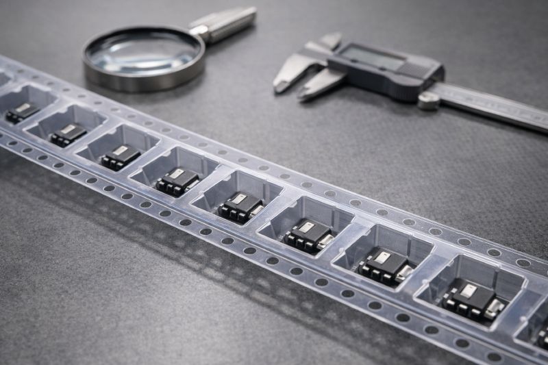
From an engineering standpoint, the defining characteristics of PC carrier tape are observed not through datasheets, but through how the tape behaves during forming, handling, and feeding. The most noticeable trait is its structural rigidity, which allows pocket geometry to remain consistent even when pocket depth increases or shapes become more complex. This rigidity directly affects how well components are constrained inside the pocket throughout transport and SMT feeding.
PC shows a strong ability to retain pocket shape under mechanical stress. During high-speed indexing, acceleration and deceleration forces are transferred through the tape. With PC, pocket walls are less prone to elastic deformation, meaning component orientation remains predictable from reel to pick-up position. This behavior becomes increasingly important as pitch tightens and placement tolerances shrink.
Another key engineering characteristic is PC’s dimensional stability during thermal exposure. While carrier tape is not exposed to extreme temperatures, localized heat from forming, sealing, and prolonged feeder operation can subtly affect pocket dimensions. PC minimizes these dimensional shifts, supporting consistent pick height and vacuum engagement over long production runs.
When compared at the engineering level, the difference between PC and PS or PET is not incremental—it is behavioral. PS tends to favor manufacturability and cost, while PET balances flexibility and robustness. PC, however, prioritizes shape fidelity and process repeatability, particularly for deep pockets, fine-pitch layouts, and components with non-uniform mass distribution.
These observed behaviors are why searches related to pc carrier tape properties often originate from engineers troubleshooting stability, not procurement teams comparing materials.
Engineering Scenarios Where PC Carrier Tape Performs Best
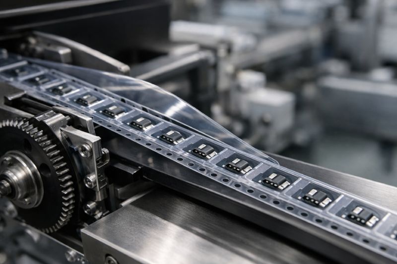
PC carrier tape shows its value most clearly in process-driven engineering scenarios where small mechanical variations translate directly into yield loss or placement instability. These are not edge cases—they are environments where standard materials begin to expose their limits.
One common scenario is high-speed SMT lines. As feeder speeds increase, the carrier tape experiences rapid indexing forces and repeated stop–start cycles. In these conditions, materials with lower rigidity may allow subtle pocket distortion, leading to inconsistent component presentation. PC maintains pocket geometry under these dynamic loads, helping ensure repeatable pick-up behavior even at elevated speeds.
Another scenario involves tight pitch and high placement accuracy requirements. When pitch tolerance margins are narrow, any cumulative deviation in pocket position or shape can affect placement accuracy downstream. PC’s ability to hold dimensional consistency supports predictable component alignment, reducing the need for feeder tuning or corrective offsets.
PC also excels with components that have complex geometry—such as uneven mass distribution, tall profiles, or asymmetrical outlines. These components are more sensitive to pocket wall flex and bottom deformation. PC’s stiffness helps stabilize component orientation throughout transport and feeding, lowering the risk of rotation, tilt, or partial lift during vacuum pick-up.
Finally, PC is frequently selected in yield-critical production environments, where defect escape is costly and process variation must be tightly controlled. In these cases, carrier tape is treated as a functional part of the process rather than a consumable. Engineers choose PC not to improve one metric, but to reduce uncertainty across the entire packaging and placement chain.
These scenarios explain why engineers searching for PC carrier tape are typically addressing performance boundaries, not material substitution.
Advantages of PC Carrier Tape in Precision Applications
The advantages of PC carrier tape become apparent when precision is treated as a system requirement, not a single parameter. Its primary benefit lies in how consistently it preserves pocket geometry from forming through final placement. This consistency directly supports stable component positioning, which is essential when placement accuracy margins are tight and process windows are narrow.
In high-speed feeder operation, PC’s rigidity helps reduce micro-variation caused by repeated mechanical stress. As the tape indexes, stops, and advances thousands of times, materials with more flex can introduce slight but cumulative changes in how components sit or present. PC minimizes these effects, contributing to repeatable pick height and orientation over long production runs.
Another advantage is PC’s reliability in precision-driven projects where rework, tuning, or yield loss carries significant cost. Engineers often favor PC not because it improves nominal performance, but because it reduces variability. Fewer adjustments, fewer unexpected feeding issues, and more predictable behavior across batches translate into smoother line operation.
This is why, in high-end applications, teams may intentionally accept higher material cost. The trade-off is justified when carrier tape stability helps protect component value, maintain throughput, and reduce the risk of hidden process losses. In this context, PC’s advantage is not about being “better,” but about being more dependable when precision truly matters.
Why PC Carrier Tape Is Not Always the Right Choice
Despite its strengths, PC carrier tape is not a universal solution, and applying it without clear engineering justification can introduce unnecessary cost and complexity. Its limitations become evident in applications where process demands do not require high structural rigidity or tight dimensional control.
One common mismatch is cost-sensitive projects. PC material and forming processes are inherently more expensive than those used for PS or PET. When component value is low or margins are tight, the added stability of PC may not translate into measurable process benefit. In such cases, the material cost outweighs the incremental gain in consistency.
PC is also excessive for low-speed SMT lines or manual-assisted feeding environments. When indexing forces are modest and placement speeds are forgiving, simpler materials can perform reliably without introducing risk. The same applies to components with simple geometry, shallow pockets, or wide pitch, where pocket deformation is unlikely to affect orientation or pick-up behavior.
Another consideration is design overengineering. Using PC where deep pockets, complex outlines, or tight tolerances are not required can complicate forming and increase lead time without improving outcomes. Engineers may find that PS or PET delivers adequate performance with greater flexibility in design iteration.
Understanding where PC does not add value is critical. Selecting PC without a performance-driven reason can reduce cost efficiency without improving yield, making material selection less about engineering and more about assumption.
How to Decide If PC Carrier Tape Is Right for Your Application
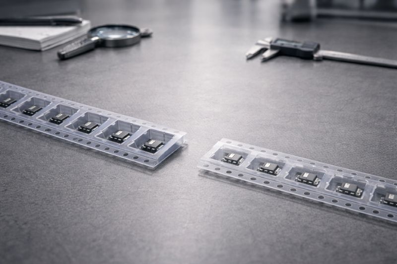
Determining whether PC carrier tape is the appropriate choice requires framing the decision around process risk, not material preference. Engineers typically arrive at PC after identifying where instability, variation, or tolerance stacking affects placement performance.
If placement accuracy is critical, PC becomes a strong candidate. When components must be presented to the pick head with minimal positional variation, the pocket shape stability of PC helps maintain consistent pick-up conditions. This is especially relevant when fine pitch and tight nozzle alignment leave little room for compensation.
If SMT line speed is high, PC is often preferred. Higher indexing speeds amplify mechanical stress on the carrier tape, increasing the likelihood of pocket distortion in more flexible materials. PC’s rigidity supports repeatable feeding behavior under these dynamic conditions, reducing the need for frequent feeder adjustments.
If cost is the primary constraint, PC should be reconsidered. When yield impact from carrier tape variation is minimal, alternative materials may offer sufficient performance at lower cost. Likewise, if component geometry is simple and does not demand deep or complex pockets, PC may add no practical benefit.
A practical decision approach is to ask whether carrier tape behavior influences yield, placement stability, or process tuning. If the answer is yes, PC is often justified. If not, its use may represent unnecessary over-specification rather than sound engineering judgment.
PC vs PS vs PET Carrier Tape: Material Selection Direction
Choosing between PC, PS, and PET carrier tape is less about ranking materials and more about matching material behavior to process intent. Each material serves a distinct engineering direction, and understanding these directions helps avoid both under- and over-specification.
PC carrier tape is selected when precision and stability dominate the decision logic. Its role is to minimize variation in pocket geometry, component orientation, and feeding behavior under demanding conditions. PC is typically chosen after other materials expose limits—such as pocket deformation at speed, instability with deep pockets, or sensitivity to tight placement tolerances. It represents a control-oriented choice, prioritizing repeatability over flexibility or cost.
PET carrier tape occupies the balanced middle ground. It offers a combination of strength, flexibility, and process adaptability that suits a wide range of SMT applications. PET is often used when performance requirements are moderate but consistency still matters. It handles standard pocket depths and common geometries well, making it a practical option when both engineering reliability and cost efficiency are considered.
PS carrier tape follows a cost- and maturity-driven direction. It is widely used in stable, well-understood applications where component geometry is simple and process parameters are forgiving. PS supports efficient mass production and fast iteration, but it is more sensitive to mechanical stress and pocket deformation as requirements tighten.
The key distinction is directional:
PC controls variation, PET balances constraints, and PS optimizes economy. Selecting correctly means aligning material behavior with the actual risks present in the SMT process, rather than assuming one material universally outperforms the others.
PC Carrier Tape from a Manufacturing Perspective
From a manufacturing standpoint, PC carrier tape places higher demands on process control than PS or PET, and this directly influences its consistency in real-world use. The performance advantages associated with PC do not come automatically from the material itself—they are realized only when forming conditions, tooling, and process stability are tightly managed.
PC forming requires precise temperature control and stable embossing conditions. Its rigidity means that pocket shape is less forgiving to variation in tooling alignment or forming pressure. As a result, manufacturers producing PC carrier tape must rely on well-controlled forming windows and experienced process tuning to achieve consistent pocket geometry across long production runs.
This is also why PC carrier tape shows strong batch-to-batch repeatability when manufactured correctly. Once the forming process is stabilized, PC tends to reproduce pocket dimensions with minimal drift, even in extended runs. In contrast, materials that are easier to form may show gradual variation as tooling wears or conditions fluctuate.
Another manufacturing consideration is process discipline rather than material flexibility. PC does not tolerate shortcuts in setup or rapid parameter changes. However, when production is structured around controlled tooling, validated forming parameters, and disciplined quality checks, PC delivers predictable results at scale.
This manufacturing reality explains why PC carrier tape is often associated with specialized or source-level manufacturers. Its stability in application is a reflection of manufacturing rigor, not merely material selection, and this distinction is critical for engineers evaluating long-term process reliability.
Custom PC Carrier Tape: Design & Engineering Considerations
Standard PC carrier tape solutions cover many high-precision needs, but there are situations where custom design becomes unavoidable. This typically occurs when component geometry, tolerance requirements, or process conditions push beyond what standard pocket libraries can reliably support.
One common trigger is non-standard component geometry. Components with unusual outlines, uneven mass distribution, or critical orientation constraints may require pocket shapes that precisely control contact points rather than relying on generic cavity forms. In these cases, PC’s rigidity supports the design intent, but pocket geometry must be engineered carefully to avoid over-constraint or stress concentration.
Pitch and tolerance trade-offs are another key consideration. While PC enables tight dimensional control, tighter tolerances increase sensitivity to tooling precision and forming variation. Engineers must balance pocket accuracy against manufacturability, ensuring that tolerances are realistic for stable mass production rather than optimized only for prototypes.
Prototyping and validation play a critical role in custom PC projects. Sampling is not optional. Trial runs allow engineers to observe real feeding behavior, component stability, and peel performance before committing to full-scale production. Adjustments at this stage are far less costly than correcting issues after line integration.
In custom applications, PC carrier tape should be viewed as a co-engineered solution, where material choice, pocket design, and process validation are aligned to support long-term stability rather than short-term specification targets.
Typical Applications of PC Carrier Tape
PC carrier tape is most often applied in environments where component value, placement accuracy, and process stability justify a higher level of material control. Rather than being spread across many industries, its use is concentrated in scenarios where carrier tape behavior directly influences yield and reliability.
In semiconductor and IC packaging, PC is frequently selected for components with fine pitch, strict orientation requirements, or deep pocket designs. Here, pocket shape retention and dimensional consistency help ensure predictable feeding and stable pick-up across long production cycles.
High-density SMT assemblies are another common application. As board layouts become more compact and placement tolerances tighten, even minor variation in component presentation can affect placement accuracy. PC carrier tape supports consistent component positioning, reducing cumulative errors in dense assemblies.
Within automotive electronics, PC is often chosen for components that must meet high reliability standards and endure extended production runs. Stability and repeatability are prioritized to minimize process drift and reduce the risk of latent defects.
PC is also used for precision connectors and similar components with complex geometry or orientation sensitivity. In these cases, the carrier tape functions as an active part of the placement process, maintaining component stability until the exact moment of pick-up.
Across these applications, PC carrier tape is applied selectively—where precision requirements are explicit and the cost of instability is high.
Summary: When PC Carrier Tape Is the Right Engineering Choice
PC carrier tape is fundamentally a precision-driven material choice, defined by its ability to control variation rather than minimize cost. Its engineering value lies in maintaining pocket geometry, component orientation, and feeding stability when process conditions become demanding.
It is best suited for applications involving high-speed SMT, tight pitch, complex component geometry, or yield-critical production, where small inconsistencies can lead to measurable losses. At the same time, PC has clear boundaries and offers limited benefit in low-speed, cost-sensitive, or structurally simple applications.
Engineering selection guidance:
Choose PC carrier tape when carrier tape behavior directly affects placement accuracy or process stability. When it does not, simpler materials are often the more efficient and appropriate solution.



 Emial
Emial John Mr


