








Common Carrier Tape Problems in SMT Packaging: Causes, Symptoms & Engineering Considerations
Why Carrier Tape Problems Occur in SMT Packaging
Carrier tape problems in SMT packaging rarely originate from a single isolated mistake. They emerge because SMT is a high-speed, continuous, and tightly coupled system, where carrier tape functions as an active part of the feeding mechanism—not a passive container.
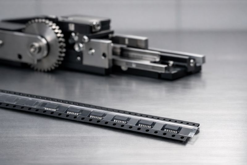
In modern SMT lines, tapes move at high acceleration, index precisely with feeders, and interact dynamically with cover tape, pockets, sprocket holes, and component geometry. Within this environment, small deviations that appear acceptable in static inspection—such as minor pitch variation, pocket stiffness differences, or peel-force imbalance—can be amplified into visible failures during production.
This is why carrier tape issues often feel inconsistent or intermittent. The problem is not that the tape is “out of spec,” but that the tape, component, feeder, and process conditions are no longer working as a matched system. Understanding carrier tape problems therefore requires a system-level engineering perspective, grounded in proper carrier tape design principles and tape and reel packaging behavior under real SMT operating conditions.
Problem Category Overview
To understand carrier tape problems effectively, it helps to view them as patterns, not isolated defects. Most issues observed in SMT production fall into a small number of recurring categories, each reflecting a different part of the tape-and-feeding system where mismatch or imbalance occurs.
At a high level, common carrier tape problems can be grouped into four categories. Feeding-related problems affect how smoothly and consistently the tape advances through the feeder. Component positioning problems involve rotation, shifting, or loss of components within the pocket. Cover tape–related problems arise from peeling and sealing behavior under dynamic conditions. Finally, dimensional and tolerance-related problems emerge over long runs, where small deviations accumulate and disrupt placement accuracy.
This categorization acts as a diagnostic map. Instead of reacting to symptoms at the machine level, engineers can identify which system layer is involved and evaluate carrier tape design and tape-and-reel packaging behavior accordingly.
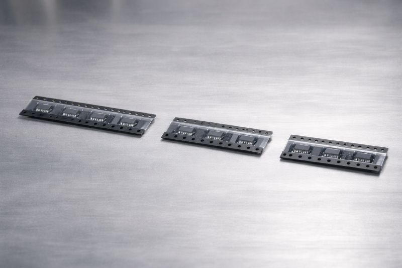
Feeding Instability and Jamming Issues
Feeding instability is one of the most visible and disruptive carrier tape problems in SMT production. Common symptoms include intermittent tape jamming, irregular index movement, and sudden feeder stoppage without an obvious mechanical fault. These issues are often mistaken for feeder defects, yet in many cases the root cause lies in the carrier tape itself.
From an engineering perspective, stable feeding depends on precise synchronization between the tape’s mechanical features and the feeder’s indexing system. Pitch inconsistency, even within nominal tolerance, can introduce cumulative indexing error at high speeds. D1 hole indexing deviation affects how accurately the feeder engages and advances the tape, increasing friction or causing momentary misalignment. In parallel, tape stiffness mismatch—too rigid or too compliant for the feeder design—can lead to poor tracking, edge climbing, or resistance during acceleration and deceleration.
These factors rarely act alone. When combined with high-speed SMT operation, small geometric or material variations can amplify into feeding instability. Understanding how pitch, sprocket hole accuracy, and tape stiffness interact is essential before attributing feeding problems solely to feeder performance.
Component Rotation, Shifting & Loss
Component rotation, shifting, or complete loss from the pocket is another frequent carrier tape problem observed during SMT handling and placement. Typical symptoms include inconsistent pick-up orientation, components rotating between stations, or parts jumping out of pockets during transport, de-reeling, or feeding. These failures often appear random, but they are usually the result of predictable mechanical imbalance.
At the core of this issue is pocket geometry mismatch. When pocket depth, wall angle, or clearance does not align with the component’s center of gravity, the component becomes sensitive to vibration and acceleration. Even when static fit appears acceptable, dynamic movement can cause rotation or lift. Inadequate retention force further reduces stability, especially for lightweight or asymmetrical components.
Cover tape behavior also plays a critical role. Peel imbalance—where the cover tape applies uneven force during opening—can disturb component position just before pick-up. When pocket design, retention force, and cover tape interaction are not engineered as a coordinated system, component stability becomes unreliable under real SMT operating conditions.
Cover Tape Peeling and Sealing Problems
Cover tape peeling and sealing problems are among the most misunderstood carrier tape issues in SMT packaging. Excessive peel force, cover tape lifting during transport, or inconsistent peeling at the feeder are often treated as sealing defects. In reality, these symptoms reflect a mismatch between dynamic peel behavior and the overall tape system.
From an engineering standpoint, cover tape is not merely a sealing layer. It is a functional element that must peel at a controlled, repeatable force while the carrier tape is moving at speed. Peel force is therefore a dynamic parameter, influenced by peel angle, peel speed, material elasticity, and adhesion uniformity. Values measured under static or laboratory conditions may not represent behavior during actual SMT operation.
Carrier tape material plays a decisive role in this interaction. Different base materials respond differently to heat, pressure, and adhesive bonding, which directly affects peel consistency. When cover tape selection is not matched to carrier tape material and pocket design, peeling instability becomes inevitable—even if sealing strength appears acceptable in isolation.
Dimensional and Tolerance-Related Problems
Dimensional and tolerance-related problems often emerge gradually, making them difficult to diagnose in early stages of SMT production. Typical symptoms include feeding drift over long runs, pocket-to-pocket misalignment, and subtle but increasing placement deviation across the reel. Unlike abrupt jamming or component loss, these issues tend to worsen with time and speed.
The key engineering principle here is that nominal dimensions are not the same as functional dimensions. While individual features such as pocket size, pitch, or sprocket hole position may fall within specification, their combined variation can accumulate. In high-speed SMT systems, this tolerance stack-up effect is amplified over hundreds or thousands of index cycles, eventually exceeding the feeder’s compensation range.
Modern SMT equipment operates with extremely tight positional windows. As line speed increases, tolerance sensitivity rises sharply, leaving little margin for cumulative error. Without considering how dimensional tolerances interact across the entire carrier tape, long-run stability and placement accuracy become increasingly difficult to maintain.
Material-Related Carrier Tape Problems
Material-related carrier tape problems are often misunderstood because the material itself may appear “correct” on paper. A common misconception is that selecting a known material automatically ensures performance. In practice, many failures occur because the material is applied outside its functional boundary, not because it is inherently unsuitable.
For example, using PS carrier tape in projects that demand high dimensional stability or tight tolerance control can lead to deformation, feeding inconsistency, or pocket relaxation under temperature and mechanical stress. Conversely, selecting PET or PC carrier tape for extremely cost-sensitive applications may introduce unnecessary stiffness, higher forming constraints, or sealing incompatibility with standard cover tapes.
From an engineering perspective, every carrier tape material has a defined performance envelope. Factors such as stiffness, elastic recovery, thermal response, and forming behavior directly influence pocket stability, feeding smoothness, and cover tape interaction. When operating conditions—such as SMT speed, component mass, or environmental temperature—approach the limits of a material, problems begin to surface even if all dimensions remain nominal.
Understanding material-related carrier tape problems therefore requires shifting the question from “Is this the right material?” to “Is this material being used within its engineered limits for this specific application?”
Why Many Carrier Tape Problems Are Misdiagnosed
Many carrier tape problems persist not because they are difficult to fix, but because they are frequently misdiagnosed at the system level. A common mistake is treating visible symptoms as isolated faults rather than signals of broader interaction issues within the SMT process.
One typical misjudgment is attributing feeding instability directly to the feeder, leading to repeated machine adjustments or hardware replacement. In reality, the feeder is often reacting correctly to inconsistent pitch, sprocket hole deviation, or tape stiffness variation. Another frequent error is modifying a single parameter—such as peel force or pocket depth—without considering how that change affects component stability, cover tape behavior, and indexing accuracy simultaneously.
Carrier tape performance is inherently collaborative. Tape geometry, material properties, feeder mechanics, and process speed operate as a linked system. When one element is adjusted in isolation, new problems may emerge elsewhere. Recognizing carrier tape issues as system-level mismatches rather than single-point defects is a critical step toward reliable diagnosis and sustained SMT line stability.
When Carrier Tape Problems Indicate the Need for Custom Design
Not all carrier tape problems can be resolved through parameter adjustment or material substitution. In certain cases, recurring issues signal that the standard tape configuration itself is no longer compatible with the application. Recognizing this boundary is essential for avoiding repeated trial-and-error on the SMT line.
One key indicator is problem repetition. If the same feeding or component stability issues persist despite changes to peel force, feeder settings, or handling conditions, the limitation is likely structural. Another sign appears when problems occur only at higher SMT speeds, suggesting that the tape performs adequately under static or low-speed conditions but fails dynamically. Projects with high sensitivity to yield loss, such as fine-pitch or orientation-critical components, further reduce tolerance for marginal tape performance.
In these situations, custom carrier tape design becomes an engineering requirement rather than an optimization option. Adjusting pocket geometry, pitch strategy, retention characteristics, or material selection at the design stage allows the tape to be engineered as part of the overall feeding system, rather than forced to adapt after failures occur.
How to Prevent Carrier Tape Problems (Engineering-Level)
Preventing carrier tape problems is fundamentally an engineering design exercise, not a troubleshooting routine. The most effective prevention happens before the tape ever reaches the SMT line, when system interactions can still be shaped rather than corrected.
The first layer is correct material selection, based not only on cost or availability, but on stiffness, thermal behavior, and forming stability under actual SMT operating conditions. The second layer is proper interpretation of specifications. Industry standards define dimensional limits, but they do not guarantee functional compatibility at high speed or under dynamic load. Understanding how pitch, pocket geometry, and sprocket hole accuracy behave together is critical.
Most importantly, carrier tape should be evaluated as part of the complete feeding system during the design phase. Pocket design must reflect component center of gravity, retention needs, and cover tape interaction. When these factors are addressed early—guided by carrier tape design principles rather than post-failure adjustments—many common problems never surface.
At the engineering level, prevention means designing for system compatibility, not relying on downstream correction once instability appears.
Summary: Carrier Tape Problems Are System-Level Issues
Carrier tape problems in SMT packaging are rarely the result of something being “made wrong.” More often, they arise because otherwise acceptable elements are combined into a system that no longer works in balance. Feeding instability, component movement, peeling inconsistency, and dimensional drift all point to the same underlying reality: the tape, component, feeder, and process conditions must function as a coordinated whole.
When carrier tape is treated as a passive consumable, problems tend to be addressed reactively. When it is engineered as part of the feeding system, many of those problems can be prevented entirely. Shifting the focus from post-line correction to system-level design alignment is what separates temporary fixes from long-term SMT stability.
For engineering teams evaluating persistent carrier tape issues, the next step is not repair—but reconsideration of design, material, and packaging strategy at the system level.



 Emial
Emial John Mr


