








EIA-481 Standard Explained: Carrier Tape Dimensions, Tolerances & SMT Compliance Guide
Introduction
In modern SMT (Surface Mount Technology) manufacturing, automation depends on precision at every stage—including how components are packaged and delivered to the pick-and-place machine. This is where the EIA-481 standard plays a critical role.
EIA-481 defines the dimensional, mechanical, and performance requirements for carrier tape, cover tape, and reel packaging used in tape-and-reel systems. It ensures that components can be consistently fed, positioned, and placed without interruption.

For engineers and procurement teams, understanding this standard is not just about compliance—it directly impacts feeder compatibility, placement accuracy, production yield, and long-term supply chain reliability. Poorly designed or non-compliant carrier tape can lead to misfeeds, machine downtime, and even component damage.
This guide explains the EIA-481 standard in detail and shows how to apply it when selecting or designing carrier tape solutions.
What Is the EIA-481 Standard?
EIA-481 is an industry standard developed by the Electronic Industries Alliance (EIA) to define the requirements for tape-and-reel packaging used in automated electronic assembly.
The standard (commonly referred to as EIA-481-D or later revisions) covers three main components:
-
Carrier tape dimensions and structure
-
Cover tape sealing and peel characteristics
-
Reel size, geometry, and winding direction
Its purpose is to ensure interoperability between component manufacturers, packaging suppliers, and SMT assembly lines. By following a unified specification, different suppliers can produce packaging that works seamlessly across global production environments.
Unlike general product descriptions, EIA-481 does not explain what carrier tape is—it defines how it must be designed and manufactured to function reliably in automated systems.
Why EIA-481 Matters in SMT Manufacturing
EIA-481 is not just a technical reference—it is a foundation for stable, high-speed SMT production.
Equipment Compatibility
Pick-and-place machines rely on standardized feeder systems. These feeders are designed to work with carrier tapes that strictly follow EIA-481 dimensions. Even small deviations can result in feeding errors or misalignment.
Production Yield and Accuracy
Precise pocket dimensions and positioning ensure that components are consistently presented to the vacuum nozzle. This directly affects pick accuracy and placement reliability.
Supply Chain Consistency
In global manufacturing, components and packaging often come from multiple suppliers. EIA-481 ensures that all materials conform to a unified standard, reducing variability and integration issues.
Quality Assurance and Audits
OEMs and EMS providers often require EIA-481 compliance as part of their quality control process. Non-compliant packaging can fail incoming inspection or disrupt production qualification.
| Without EIA-481 Compliance | With EIA-481 Compliance |
|---|---|
| Frequent feeding errors | Stable, repeatable feeding |
| Component misalignment | Accurate pick-and-place |
| Machine downtime | High production efficiency |
| Supplier inconsistency | Interchangeable sourcing |
Key Dimensions Defined in EIA-481
The EIA-481 standard defines a series of critical dimensions that control how carrier tape interacts with feeders and components.
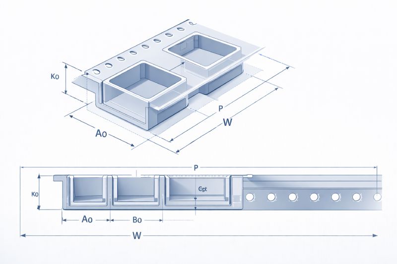
Carrier Tape Width (W)
Carrier tape width determines compatibility with feeder lanes. Common widths include:
-
8 mm
-
12 mm
-
16 mm
-
24 mm
-
32 mm
-
44 mm
-
56 mm
The width is selected based on component size and spacing requirements. Choosing the correct width ensures proper guidance and stability during feeding.
Pocket Pitch (P)
Pocket pitch refers to the distance between adjacent component pockets. Standard pitches include:
-
2 mm
-
4 mm
-
8 mm
The pitch must align with feeder indexing mechanisms. Incorrect pitch can result in synchronization errors between tape movement and pick operations.
Pocket Dimensions (A0, B0, K0)
These are the most critical parameters for component protection and positioning:
-
A0 (Length) – pocket length
-
B0 (Width) – pocket width
-
K0 (Depth) – pocket depth
These dimensions must be carefully designed to:
-
Prevent component movement
-
Avoid excessive tightness that may damage parts
-
Ensure correct pick position
Tolerance control is especially important here, as even small deviations can affect pick accuracy.
Sprocket Hole Dimensions
Sprocket holes are used to drive the tape through the feeder system.
Key specifications include:
-
Standard pitch: 4 mm
-
Hole diameter and position relative to pocket
-
Alignment tolerance
These holes must maintain precise spacing and alignment to ensure smooth indexing. Any deviation can cause feeding interruptions or misalignment.
Tolerance Requirements in EIA-481
While nominal dimensions define the structure, tolerances determine real-world performance.
EIA-481 specifies allowable variation ranges for key dimensions, typically in the range of:
-
±0.05 mm
-
±0.1 mm
These tolerances affect several critical factors:
Pick Position Accuracy
If pocket dimensions vary beyond tolerance, components may shift, leading to incorrect pick positions.
Nozzle Alignment
Precise alignment between pocket center and feeder indexing ensures reliable vacuum pickup.
Component Stability
Proper tolerance prevents components from tilting, flipping, or overlapping within the pocket.
Material Influence
Different materials affect tolerance stability:
-
PS (Polystyrene) – cost-effective but less rigid
-
PET (Polyethylene Terephthalate) – better dimensional stability
-
PC (Polycarbonate) – high precision and durability
Material selection must align with tolerance requirements and application conditions.
Cover Tape and Sealing Standards
EIA-481 also defines requirements for cover tape performance, particularly in sealing and peeling behavior.
Peel Force
Typical peel force range:
-
0.1 N – 1.3 N
This ensures:
-
Easy removal during feeding
-
Secure sealing during transport
Too low: components may escape
Too high: feeder may jam or tear the tape
Peel Angle
Standard peel angles include:
-
165°
-
180°
The peel angle affects how the cover tape separates during feeding and must be compatible with feeder design.
Sealing Methods
-
Heat sealing
-
Pressure sealing
Each method must provide consistent adhesion without damaging the carrier tape or components.
| Parameter | Requirement |
|---|---|
| Peel force | 0.1–1.3 N |
| Peel angle | 165°–180° |
| Seal method | Heat or pressure |
Reel Specifications and Packaging Requirements
The standard also defines reel dimensions to ensure compatibility with storage systems and feeders.
Common Reel Sizes
-
7-inch reels
-
13-inch reels
Key Parameters
-
Hub diameter
-
Reel width
-
Maximum weight
-
Winding direction (clockwise or counterclockwise)
Proper reel design ensures smooth loading into feeders and efficient handling in automated storage systems.
Common Compliance Issues and How to Avoid Them
Even when designs follow EIA-481, manufacturing inconsistencies can lead to non-compliance.
Common Issues
-
Incorrect pocket dimensions
-
Warping or deformation of tape
-
Inconsistent peel force
-
Misaligned sprocket holes
How to Avoid Them
Incoming Inspection
Verify dimensions and peel force before production use.
Supplier Qualification
Choose suppliers with proven EIA-481 compliance and process control.
Pilot Run Testing
Validate performance in actual SMT conditions before mass production.
These steps significantly reduce production risk and ensure consistent performance.
How to Verify EIA-481 Compliance
Compliance verification requires both measurement and functional testing.
Measurement Methods
-
Optical measurement systems
-
Vision inspection tools
-
Profile projectors
Functional Testing
-
Peel force testing
-
Feeding tests on SMT machines
Key Checks
-
Pocket dimensions (A0, B0, K0)
-
Pitch accuracy
-
Sprocket hole alignment
-
Cover tape performance
A combination of dimensional inspection and real-world testing provides the most reliable validation.
How to Choose an EIA-481 Compliant Carrier Tape Supplier
Selecting the right supplier is critical for maintaining compliance and production stability.
What to Look For
1. Tolerance Reporting
Suppliers should provide detailed measurement reports for key dimensions.
2. Custom Design Capability
Ability to optimize pocket design for specific components.
3. SMT Application Experience
Suppliers with real SMT knowledge can anticipate feeding issues and design accordingly.
4. Sampling and Validation Support
Quick sample turnaround and engineering support for validation.
Why It Matters
A reliable supplier does more than meet specifications—they help reduce risk, improve yield, and support long-term production stability.
Typical next steps for buyers:
-
Request engineering drawings
-
Evaluate sample carrier tape
-
Review tolerance and inspection reports
Conclusion: EIA-481 as the Foundation of Reliable SMT Packaging
The EIA-481 standard is far more than a dimensional guideline—it is the foundation of consistent, high-performance SMT packaging.
By defining how carrier tape, cover tape, and reels must be designed and manufactured, it ensures compatibility across machines, suppliers, and production environments.
For engineers, it guarantees precision and repeatability.
For procurement teams, it reduces risk and improves sourcing flexibility.
For manufacturers, it enables stable, high-efficiency production.
Understanding and applying EIA-481 is essential for anyone involved in electronic component packaging.



 Emial
Emial John Mr


