








Tape Pitch in Carrier Tape: Definition, Standards & Selection Guide
Introduction
In SMT (Surface Mount Technology) manufacturing, even small dimensional parameters can have a major impact on production efficiency and yield. One of the most critical yet often misunderstood parameters is tape pitch in carrier tape packaging. Tape pitch directly influences how components are spaced, fed, and picked during automated assembly processes.
Whether you are sourcing standard carrier tape or developing a custom solution, understanding tape pitch is essential for ensuring compatibility with pick-and-place machines, preventing feeding errors, and optimizing material usage. It is also closely tied to industry standards such as EIA-481, which define how carrier tapes should be designed for reliable automation.
In this guide, we’ll break down what tape pitch is, how it works, how to calculate it, and how to choose the right pitch for your components—so you can improve both performance and cost efficiency in your SMT production.

What Is Tape Pitch in Carrier Tape? (Core Definition)
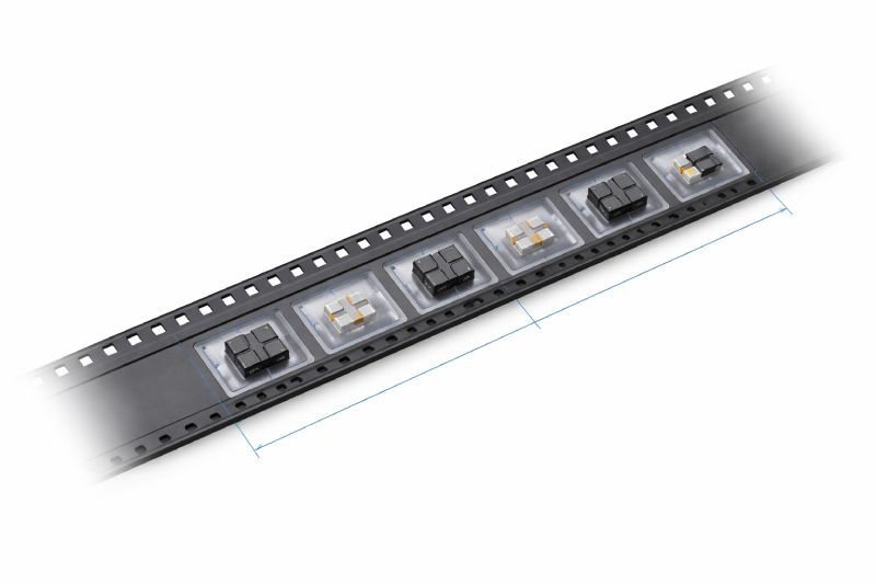
Tape pitch refers to the center-to-center distance between adjacent component pockets in a carrier tape. It determines how far apart each component is positioned along the tape and directly affects how the tape advances through SMT feeders.
In most cases, tape pitch is measured in millimeters (mm) and follows standardized increments to ensure compatibility with automated equipment.
Key characteristics of tape pitch:
- Measured from the center of one pocket to the center of the next
- Typically standardized (e.g., 4 mm, 8 mm, 12 mm, 16 mm)
- Determines indexing steps in feeder systems
- Directly impacts pick-and-place timing and accuracy
In simple terms, tape pitch defines the rhythm of component feeding. If this spacing is incorrect, even the most advanced SMT equipment can experience misfeeds, skipped components, or alignment issues.
Standard Tape Pitch Values (EIA-481 Explained)
Carrier tape dimensions, including pitch, are governed by the EIA-481 standard to ensure interoperability across machines and suppliers.
The most fundamental concept is that 4 mm is the base indexing pitch, which aligns with the spacing of sprocket holes used by feeder systems.
Typical Tape Pitch Values
| Tape Width | Typical Pitch | Common Applications |
|---|---|---|
| 8 mm | 4 mm | Resistors, capacitors, small ICs |
| 12 mm | 4–8 mm | Medium ICs, sensors |
| 16 mm | 8 mm | Larger ICs |
| 24 mm+ | 12–16 mm | Connectors, large components |
Key Engineering Insights
- 4 mm pitch is the industry baseline because sprocket holes are spaced at 4 mm intervals
- Larger components require increased pitch to avoid collision and ensure safe pocket spacing
- Tape pitch must synchronize with sprocket hole indexing for smooth feeding
- Non-standard pitch designs may require custom tooling and validation
Following EIA-481 ensures that your carrier tape will function seamlessly across different SMT lines and equipment manufacturers.
Why Tape Pitch Matters in SMT Manufacturing
Tape pitch is not just a dimensional detail—it is a critical factor in production stability and efficiency.
1. Feeding Accuracy
Proper pitch ensures that each component aligns precisely with the pick-up position. Incorrect spacing can cause:
- Missed picks
- Double picks
- Component misalignment
2. Machine Synchronization
SMT feeders rely on precise indexing movements. Tape pitch must match the feeder’s step size to maintain consistent operation.
3. Placement Speed
High-speed SMT lines depend on predictable component spacing. Incorrect pitch can slow down machines or cause stoppages.
4. Component Protection
Adequate spacing prevents components from:
- Touching each other
- Tilting or rotating inside pockets
- Getting damaged during transport
5. Yield and Cost Efficiency
Even minor pitch errors can lead to:
- Increased defect rates
- Machine downtime
- Higher scrap and rework costs
In short: incorrect tape pitch translates directly into production risk and financial loss.
How Tape Pitch Is Measured and Calculated
Measuring tape pitch is straightforward, but precision is essential.
Measurement Method
Tape pitch is determined by measuring the distance between the centers of two adjacent pockets.
Formula
Pitch (P) = Center-to-center distance between pockets
Tools Used
- Digital calipers
- Optical measurement systems
- Vision inspection equipment
Important Considerations
- Always measure multiple intervals to avoid single-point error
- Check for cumulative tolerance deviations across longer tape lengths
- Ensure alignment with sprocket hole positioning
Tolerance and Cumulative Error
In high-volume production, even a small deviation (e.g., ±0.05 mm) can accumulate over hundreds of pockets, leading to feeder misalignment.
This is why precision manufacturing and strict quality control are critical in carrier tape production.
Tape Pitch vs Pocket Pitch vs Sprocket Pitch
These terms are often used interchangeably, but they have distinct meanings.
| Term | Definition | Function |
|---|---|---|
| Tape Pitch | Distance between pocket centers | Defines component spacing |
| Pocket Pitch | Same as tape pitch (often interchangeable) | Used in design terminology |
| Sprocket Pitch | Distance between feed holes (4 mm standard) | Controls feeder indexing |
Key Differences
- Tape pitch = component spacing
- Sprocket pitch = machine movement reference (fixed at 4 mm)
- Tape pitch must align with sprocket pitch multiples
Understanding this relationship is essential for ensuring compatibility between tape design and SMT equipment.
How to Choose the Right Tape Pitch for Your Components
Selecting the correct tape pitch requires balancing component size, machine compatibility, and production efficiency.
Key Factors to Consider
1. Component Size
- Small SMD components → typically 4 mm pitch
- Medium-sized ICs → 4–8 mm
- Large components → 8–16 mm or more
2. Component Geometry
Irregular shapes may require increased spacing to prevent interference.
3. Pick-and-Place Speed
High-speed lines benefit from standardized pitch values for consistent feeding.
4. Feeder Compatibility
Ensure pitch aligns with feeder indexing increments (usually multiples of 4 mm).
5. Orientation Requirements
Some components require specific orientation, affecting pocket layout and pitch.
Quick Selection Checklist
- Use 4 mm pitch for most small electronic components
- Increase pitch for larger or fragile components
- Always validate against feeder specifications
- Consider custom pitch for non-standard designs
If your component does not fit standard pitch rules, a custom carrier tape design is often the best solution.
Common Tape Pitch Design Mistakes (and How to Avoid Them)
Even experienced engineers can overlook critical pitch-related issues.
1. Pitch Too Small
Problem: Components interfere or overlap
Result: Feeding errors and damage
Solution: Increase spacing based on component dimensions
2. Pitch Too Large
Problem: Wasted material and higher packaging cost
Solution: Optimize spacing without compromising safety
3. Misalignment with Sprocket Holes
Problem: Feeder cannot index correctly
Solution: Ensure pitch is a multiple of 4 mm
4. Ignoring Tolerance
Problem: Cumulative errors over long reels
Solution: Apply strict dimensional control and inspection
Avoiding these mistakes can significantly improve production stability and reduce costs.
Tape Pitch in Custom Carrier Tape Design
Standard pitch values do not always meet the needs of modern electronic components, especially in advanced or specialized applications.
When Custom Pitch Is Required
- Unusual component shapes
- Sensitive or fragile components
- High-density packaging requirements
- Non-standard SMT processes
Engineering Considerations
- Tooling design and cost
- Material selection (PS, PET, PC)
- Prototyping and validation
- Compatibility with existing feeders
MOQ vs Flexibility
Custom designs often involve:
- Higher initial tooling cost
- MOQ requirements
- Longer lead times
However, they provide:
- Improved feeding reliability
- Better component protection
- Optimized production efficiency
For many manufacturers, the long-term benefits outweigh the initial investment.
FAQs About Tape Pitch in Carrier Tape
1. What is the most common tape pitch?
The most common tape pitch is 4 mm, especially for small SMD components like resistors and capacitors.
2. Is tape pitch always 4 mm?
No. While 4 mm is the base increment, larger components require pitches such as 8 mm, 12 mm, or 16 mm.
3. Can tape pitch be customized?
Yes. Custom carrier tape designs can use non-standard pitch values to accommodate specific component requirements.
4. What happens if tape pitch is incorrect?
Incorrect pitch can cause feeding errors, machine stoppages, misalignment, and increased defect rates.
5. How does pitch affect SMT speed?
Proper pitch enables smooth, high-speed feeding. Incorrect pitch can slow down production or cause frequent interruptions.
Conclusion: Why Tape Pitch Is Critical for Reliable SMT Production
Tape pitch plays a fundamental role in ensuring the efficiency, accuracy, and reliability of SMT assembly processes. From component spacing to machine synchronization, every aspect of automated production depends on getting this parameter right.
By understanding standard pitch values, measurement methods, and design considerations, manufacturers can reduce defects, improve throughput, and lower operational costs.
If your application involves unique components or high-performance requirements, investing in a properly engineered carrier tape solution—whether standard or custom—can make a significant difference in your overall production success.
Need help selecting or customizing carrier tape pitch? Working with an experienced engineering team ensures your packaging solution is optimized for performance, reliability, and cost efficiency.



 Emial
Emial John Mr


