








How Components Are Loaded into Carrier Tape: Step-by-Step Tape and Reel Process
Electronic components do not simply get dropped into carrier tape pockets. In modern SMT and semiconductor packaging, every resistor, IC, LED, sensor, or connector must be loaded into the correct pocket, in the correct orientation, and at the correct position before the tape is sealed and wound onto a reel.
If the loading process is inaccurate, the result is usually much larger than a packaging issue. Components may rotate, stand up inside the pocket, jam in the feeder, or arrive at the pick-and-place machine in the wrong orientation. Even a small loading error can create downtime, placement defects, or lost production capacity.
For this reason, component loading is one of the most important stages of tape and reel packaging. It combines carrier tape design, component handling, machine accuracy, and cover tape sealing into one controlled process.
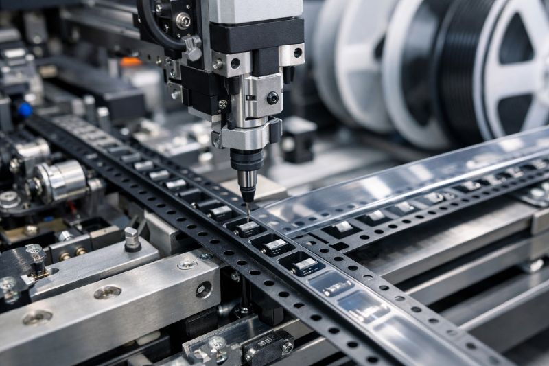
This article explains exactly how components are loaded into carrier tape, what equipment is used, the most common loading problems, and how manufacturers improve loading accuracy for high-speed SMT production.
Why Components Must Be Precisely Loaded into Carrier Tape
Carrier tape is not just a protective package. It is a precision feeding system designed to present each component to an SMT machine in a repeatable way.
When the tape enters the feeder, the machine expects every pocket to contain one component in exactly the same orientation and position. The spacing between pockets, the component height, and the way the part sits inside the cavity all affect whether the nozzle can pick the part correctly.
Precise loading provides several important benefits:
-
Prevents components from rotating or flipping during shipping
-
Keeps fragile parts stable during transport and reel handling
-
Ensures smooth feeding at high production speeds
-
Allows vacuum nozzles to pick components consistently
-
Reduces machine stops, placement errors, and scrap
| Incorrect Loading Issue | Result in SMT Line |
|---|---|
| Component rotated in pocket | Incorrect placement orientation |
| Component standing up | Pick failure or nozzle miss |
| Pocket loaded with two parts | Feeder jam |
| Component loose inside pocket | Part shifts during transport |
In high-speed SMT lines, even a small percentage of loading errors can quickly create thousands of defective placements. That is why manufacturers focus heavily on the loading process before the tape ever reaches the customer.
Step 1: Components Are Prepared Before Loading
Before a component can be inserted into carrier tape, it must first be sorted and oriented.
Most components arrive from upstream processes in bulk form. Depending on the product, they may come from molding, trimming, electrical testing, or bulk packaging operations. The loading machine cannot place these loose components directly into the tape until they are aligned in the correct direction.
Different products require different preparation methods:
-
Small chip resistors and capacitors are often supplied through vibratory bowl feeders or linear tracks.
-
ICs and semiconductor packages may arrive in trays or tubes.
-
LEDs, sensors, and optical parts often require special handling to avoid scratching or damage.
-
Irregular-shaped components may need custom fixtures before loading.
A vibratory bowl feeder is commonly used to orient large quantities of small components automatically. The bowl vibrates and guides the parts into a single line so they exit in the same direction.
For more complex products, manufacturers often use trays or magazines. These systems preserve the orientation of the component before it reaches the loading head.
Many modern tape and reel lines also include a vision inspection system before loading begins. Cameras check whether the component polarity, direction, and surface appearance are correct. If the system detects a wrong orientation or damaged part, the component is rejected before it enters the carrier tape.
This preparation stage is critical because the loading machine can only work accurately if every incoming component is already positioned correctly.
Step 2: Components Are Positioned Above the Carrier Tape Pocket
Once the components are prepared, the next step is to synchronize the component feed with the carrier tape.
The carrier tape moves forward one pocket at a time. This movement is controlled by the sprocket holes along the side of the tape. The machine indexes the tape precisely so that one empty pocket stops directly under the loading head.
Sensors detect the exact position of the sprocket holes and confirm that the tape has advanced the correct distance. If the tape moves too far or not far enough, the component may miss the pocket completely.
The indexing distance depends on the pocket pitch of the tape:
-
4 mm pitch for very small passive components
-
8 mm, 12 mm, or larger pitch for larger semiconductor packages
-
Custom pitch for special or oversized components
For example, a 4 mm pitch tape must move exactly one 4 mm increment before the next component is inserted. If the indexing accuracy is off by even a fraction of a millimeter, the part may land partly outside the cavity.
At the same time, the component handling system must move the next part above the correct pocket. The loading head, vacuum nozzle, or gripper waits until the tape stops, then lowers the component into the cavity.
The timing between component feed and tape movement is extremely important. If the machine runs too fast, the component may be released before the pocket is in position. If it runs too slowly, production speed drops and the line becomes inefficient.
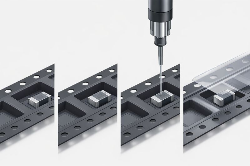
Step 3: Components Are Inserted into the Pocket
After the pocket is aligned, the actual loading process begins.
Most automatic tape and reel systems use a vacuum nozzle or a mechanical gripper to hold the component. The loading head lowers the part into the carrier tape pocket and releases it gently.
The component must sit flat and centered inside the cavity. It cannot tilt, rotate, or extend above the top edge of the tape. The pocket dimensions are designed specifically to support the component and hold it in the correct orientation.
In some systems, a small amount of air pressure or a light mechanical press is used after insertion. This helps the component settle fully into the pocket before the cover tape is applied.
Loading Small Passive Components
Chip resistors, capacitors, and inductors are usually loaded at very high speed because of their small size and simple shape.
These components often use 4 mm pitch carrier tape and can be loaded at hundreds of parts per minute. However, because the parts are extremely small, the pocket dimensions must be very precise.
If the pocket is too wide, the component may rotate. If the pocket is too shallow, the part may jump out during transport.
Loading ICs and Semiconductor Packages
IC packages such as QFN, SOP, BGA, QFP, and SOT require stricter orientation control.
These parts usually have a defined pin direction or polarity mark, so they must always enter the pocket in the same orientation. Many loading machines use cameras to confirm the direction before insertion.
For example, a QFN package loaded 180 degrees in the wrong direction may still fit physically into the pocket, but it will later cause placement errors on the SMT line.
Loading Fragile or Irregular Components
Some components are more difficult to load because of their shape or sensitivity.
LEDs, optical sensors, MEMS devices, connectors, and custom-shaped products often require slower loading speeds and specially designed pockets.
These pockets may include:
-
Rounded corners to reduce stress
-
Extra support surfaces to prevent movement
-
Anti-static material for ESD-sensitive devices
-
Deeper cavities for tall components
Pocket depth alone is not enough. The overall pocket shape must support the component so it cannot flip or move while the reel is transported.
Step 4: The Cover Tape Is Applied After Loading
After the components are loaded into the carrier tape, a cover tape is applied immediately.
The cover tape seals the components inside the pockets so they cannot escape during transport, storage, or feeder operation.
There are two main types of cover tape:
-
Heat-activated cover tape
-
Pressure-sensitive cover tape
Heat-activated cover tape uses controlled temperature and pressure to bond the tape to the carrier tape surface. Pressure-sensitive cover tape uses adhesive and does not require heat.
The sealing process must be carefully controlled. If the temperature is too low or the pressure is too weak, the cover tape may lift during shipping. If the seal is too strong, the SMT feeder may have difficulty peeling the tape during assembly.
Manufacturers usually control three key sealing parameters:
-
Temperature
-
Pressure
-
Dwell time
After sealing, the loaded tape is wound onto a reel and prepared for shipment.
Equipment Used for Carrier Tape Loading
A complete tape and reel loading line usually contains several pieces of equipment working together.
| Equipment | Function |
|---|---|
| Vibratory bowl feeder | Sorts and orients loose components |
| Vision inspection system | Checks polarity and direction |
| Indexing mechanism | Moves the carrier tape pocket-by-pocket |
| Vacuum nozzle or gripper | Places the component into the pocket |
| Sealing unit | Applies and seals the cover tape |
| Rewinder | Winds the completed tape onto the reel |
Fully automatic tape and reel machines are used for most mass-production applications. These systems can load thousands of parts per hour with very high consistency.
Semi-automatic systems are often used for medium-volume production, while manual loading may still be used for prototypes, samples, or very low-volume products.
The correct machine depends on the product geometry, production volume, tolerance requirements, and required loading speed.
Common Problems During Component Loading
Even when the loading system is automated, problems can still occur.
| Problem | Likely Cause | Result |
|---|---|---|
| Component flips in pocket | Pocket too large or poor orientation control | Feeding failure |
| Empty pocket | Loading head skipped a cycle | Missing component |
| Two parts in one pocket | Incorrect feed timing | Feeder jam |
| Damaged component | Too much insertion force | Product defect |
| Cover tape lifts | Incorrect sealing settings | Part loss during shipping |
Many loading problems actually begin with poor pocket design rather than poor machine performance.
For example, if the pocket is too large, the machine may still load the component correctly, but the part can rotate during transport. Similarly, if the pocket depth is too shallow, the component may jump out before the cover tape is sealed.
That is why manufacturers usually perform loading trials and feeder tests before mass production. The loaded tape is tested on an actual SMT feeder to confirm that the components feed smoothly and remain stable.
How Pocket Design Affects Loading Success
Pocket design has a direct effect on whether the loading process succeeds.
The width, depth, corner radius, and shape of the pocket determine how the component sits inside the carrier tape.
| Pocket Design Feature | Effect on Loading |
|---|---|
| Tight side clearance | Prevents component rotation |
| Rounded bottom surface | Helps the part sit flat |
| Correct pocket depth | Prevents jumping or tipping |
| Anti-static material | Protects sensitive devices |
An oversized pocket may allow the component to move too much. An undersized pocket may damage the component or make loading difficult.
The material of the carrier tape also matters. PET, PS, and PC carrier tape materials behave differently during forming and loading. Some materials are better for high-temperature environments, while others provide better anti-static performance.
For sensitive semiconductor products, anti-static carrier tape is often required to prevent ESD damage during loading and transport.
Automatic vs Manual Component Loading
| Method | Best For | Advantages | Limitations |
|---|---|---|---|
| Manual loading | Samples and prototypes | Flexible and low cost | Slow and inconsistent |
| Semi-automatic loading | Medium-volume production | Lower investment | More operator involvement |
| Fully automatic loading | Large-scale production | Fast and repeatable | Higher equipment cost |
Although manual loading can work for small batches, most SMT and semiconductor manufacturers prefer automatic loading because consistency is more important than speed alone.
A fully automatic system provides stable orientation, repeatable placement, and fewer operator errors.
How to Improve Carrier Tape Loading Accuracy
Manufacturers can improve loading accuracy by focusing on both the carrier tape design and the machine process.
The most effective improvements include:
-
Design the pocket based on the actual component dimensions, not only the nominal drawing
-
Use a vision system to confirm orientation before insertion
-
Maintain accurate tape indexing and sprocket hole control
-
Match the loading speed to the fragility of the component
-
Verify sealing strength and peel force after cover tape application
-
Perform feeder testing before full production begins
An experienced carrier tape supplier can also help optimize the process. Many suppliers provide sample pocket design, trial loading, and feeder testing before mass production. This reduces risk and helps ensure that the final tape and reel package will perform correctly on the SMT line.
FAQs
Can all electronic components be loaded into carrier tape?
Most electronic components can be loaded into carrier tape if the correct pocket design is used. Standard SMT parts, semiconductor packages, LEDs, connectors, and sensors can all be packaged in carrier tape.
What happens if a component is loaded in the wrong direction?
If the component orientation is wrong, the SMT machine may place the part incorrectly on the PCB. This can create assembly defects or require manual rework.
How fast can automatic carrier tape loading machines operate?
The speed depends on the component type. Small passive components may be loaded at several hundred parts per minute, while fragile or complex parts are loaded more slowly.
Why do components move inside the pocket during shipping?
Movement usually occurs because the pocket is too large, the pocket depth is incorrect, or the cover tape seal is weak.
Is manual loading acceptable for small production runs?
Yes. Manual loading is often used for prototype quantities or engineering samples. However, it is usually not suitable for mass production because the consistency is lower.
How do manufacturers verify that components are correctly loaded?
Manufacturers use cameras, vision systems, sample inspection, and SMT feeder testing to confirm that the loaded tape works correctly.
Conclusion
Loading components into carrier tape is a controlled engineering process rather than a simple packaging step. Every part must be prepared, oriented, inserted, and sealed correctly so the SMT feeder can present it accurately to the pick-and-place machine.
Successful loading depends on four key factors: correct component orientation, accurate tape indexing, proper pocket design, and reliable cover tape sealing.
When these factors are optimized, manufacturers reduce feeding problems, improve SMT efficiency, and protect components during transport.
If you are developing a new tape and reel package, the best approach is to review the component geometry early, test the pocket design, and run sample loading trials before mass production.



 Emial
Emial John Mr


