








How Paper Carrier Tape Works: Complete Guide to Structure, Feeding & SMT Packaging
In modern SMT (Surface Mount Technology) production, speed and precision are everything. Electronic components that measure only a few millimeters must move through automated assembly lines without flipping, jamming, or becoming damaged. That is where paper carrier tape plays a critical role.
Although many manufacturers and buyers are familiar with tape and reel packaging, fewer people fully understand how paper carrier tape actually works inside automated packaging and pick-and-place systems. From pocket design and sprocket hole indexing to cover tape peeling and feeder synchronization, every part of the tape is engineered to support stable high-speed production.
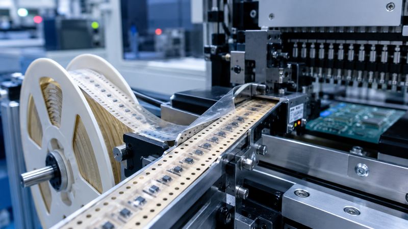
This guide explains the complete working process of paper carrier tape, how it interacts with SMT machines, what problems can occur during operation, and how manufacturers improve feeding reliability for electronic components.
The Basic Structure of Paper Carrier Tape
Paper carrier tape may look simple from the outside, but its structure is carefully designed for automated handling and precise component positioning.
Paper Base Material
Paper carrier tape is typically made from kraft paper or fiber-based paper materials that are processed for industrial packaging applications. Depending on the component requirements, the paper may also include anti-static or ESD-safe treatment to reduce electrostatic risks during transportation and feeding.
Compared with plastic embossed tape, paper tape is lightweight and cost-effective, making it especially suitable for small passive electronic components produced in high volumes.
Another advantage is environmental performance. Many manufacturers prefer paper carrier tape because it reduces plastic usage and supports more sustainable packaging solutions.
Embossed Component Pockets
The pockets or cavities are one of the most important parts of the tape. These pockets hold the electronic components securely during storage, shipping, and machine feeding.
Each cavity is designed according to:
-
component dimensions
-
thickness
-
orientation
-
pickup requirements
If the pocket is too large, components may rotate or shift during transport. If it is too small, feeding problems or component damage may occur.
Pocket consistency is especially important for automated SMT production because even slight positioning errors can affect pick-and-place accuracy.
Sprocket Holes and Indexing System
Along the edge of the paper carrier tape are evenly spaced sprocket holes. These holes allow the SMT feeder to pull the tape forward in highly controlled increments.
The feeder wheel engages with the sprocket holes and moves the tape one pitch at a time. This indexing process ensures that every component arrives at the exact pickup position under the machine nozzle.
Without accurate sprocket hole spacing, the tape may feed incorrectly, causing:
-
skipped components
-
feeder jams
-
nozzle pickup failures
-
production stoppages
Most paper carrier tapes follow EIA standard dimensions to ensure compatibility with SMT feeder systems.
Cover Tape Sealing Layer
After components are loaded into the pockets, a cover tape is sealed onto the surface of the carrier tape.
The purpose of the cover tape is to:
-
keep components inside the pockets
-
prevent contamination
-
maintain stable positioning during transportation
The sealing process must be carefully controlled. If the seal is too weak, components may escape. If the seal is too strong, the SMT feeder may struggle to peel the tape smoothly during production.
How Paper Carrier Tape Works Step by Step
To understand the real function of paper carrier tape, it is important to follow the complete operational workflow inside a tape and reel packaging process.
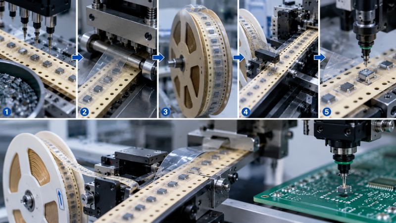
Step 1: Components Are Loaded Into the Pockets
The process begins with automatic component loading.
Electronic parts such as resistors, capacitors, LEDs, or small ICs are fed into the packaging machine through vibration bowl feeders, trays, or bulk feeding systems. The machine then places each component into the corresponding cavity of the paper tape.
At this stage, orientation control is extremely important. Components must sit correctly inside the pocket so that the SMT nozzle can pick them up accurately later.
Advanced packaging systems often use vision inspection cameras to verify:
-
component orientation
-
pocket occupancy
-
polarity direction
-
placement consistency
Any missing or incorrectly positioned components can be automatically rejected before sealing.
Step 2: Cover Tape Seals the Components
Once the pockets are filled, the cover tape is applied over the carrier tape surface.
Depending on the material and packaging design, sealing may use:
-
heat sealing
-
pressure sealing
-
adhesive-based sealing
The sealing temperature and pressure must remain stable throughout production. Poor sealing control can lead to peeling problems later during SMT feeding.
Manufacturers usually monitor peel strength carefully because it directly affects feeder performance.
Step 3: Tape Is Wound Onto Reels
After sealing, the carrier tape is wound onto reels for storage and transportation.
During winding, tension control becomes very important. Excessive tension may deform the tape or damage components, while insufficient tension may create loose winding that affects feeding stability.
The reel packaging format allows SMT factories to load thousands of components into automated production lines efficiently.
Step 4: Reel Is Installed Into SMT Feeders
At the SMT production line, operators install the reel into an SMT feeder system.
The feeder engages with the sprocket holes and advances the tape forward at precise intervals synchronized with the pick-and-place machine.
This movement is highly accurate because the nozzle pickup position must align perfectly with each component pocket.
Modern SMT lines may run at extremely high speeds, meaning the feeder must maintain stable indexing continuously without slipping or misfeeding.
Step 5: Pick-and-Place Machine Removes Components
As the tape advances, the feeder peels back the cover tape gradually to expose the components.
The pick-and-place nozzle then picks each component from the pocket using vacuum suction and places it onto the PCB.
The peeling angle and peel force are carefully controlled because unstable peeling can:
-
disturb components
-
cause pickup errors
-
generate feeder jams
-
interrupt production
Once the components are removed, the empty carrier tape continues feeding forward until the reel is fully consumed.
How Paper Carrier Tape Interacts With SMT Feeders
The relationship between carrier tape and SMT feeder systems is one of the most critical parts of automated electronics manufacturing.
Feeder Indexing Mechanism
The feeder uses sprocket wheels to engage with the tape holes and advance the tape by one pitch per cycle.
Accurate indexing ensures:
-
precise component positioning
-
stable nozzle pickup
-
reduced placement errors
-
smoother high-speed operation
Even minor dimensional inconsistencies in the tape can affect indexing precision.
Cover Tape Peeling During Feeding
As the feeder advances, the cover tape is peeled backward continuously.
Stable peeling performance depends on:
-
sealing consistency
-
adhesive stability
-
peel angle control
-
tape material quality
If peel force changes suddenly, components may jump out of pockets or shift before pickup.
Why Feeding Accuracy Matters
SMT production lines operate at extremely high speeds, and feeding interruptions are expensive.
Poor feeding performance can lead to:
-
machine downtime
-
component waste
-
nozzle errors
-
reduced production efficiency
This is why high-quality paper carrier tape manufacturing focuses heavily on dimensional accuracy and stable sealing performance.
Why Paper Carrier Tape Works Well for Small Electronic Components
Paper carrier tape is widely used for small passive components because it offers an effective balance between performance and cost.
Typical applications include:
-
chip resistors
-
multilayer ceramic capacitors
-
LEDs
-
miniature diodes
-
passive SMT components
For these products, paper tape provides:
-
lightweight handling
-
high feeding efficiency
-
low packaging cost
-
good production scalability
Compared with embossed plastic carrier tape, paper tape is often more economical for standard small-size components.
However, plastic embossed tape usually provides better rigidity and deeper cavity capability for:
-
larger ICs
-
irregular components
-
fragile electronic parts
Choosing between paper and plastic tape depends on the component size, weight, geometry, and feeding requirements.
Common Problems in Paper Carrier Tape Operation
Even small packaging inconsistencies can create major SMT feeding problems.
Component Misalignment
If pocket dimensions are inaccurate, components may rotate or shift inside the cavity during transportation.
This can lead to pickup failures and placement errors during SMT assembly.
Cover Tape Peeling Issues
Unstable sealing temperature or adhesive inconsistency can cause peeling force variation.
When the cover tape peels unevenly, components may move unexpectedly or remain partially covered during pickup.
Feeding Jams in SMT Machines
Poor sprocket hole accuracy or tape deformation can interrupt feeder movement.
Feeder jams are especially problematic in high-speed automated lines because they stop production immediately.
Static Electricity Problems
Some electronic components are sensitive to electrostatic discharge.
Without proper anti-static treatment, carrier tape materials may generate static buildup that damages sensitive devices during packaging or feeding.
How Manufacturers Improve Paper Carrier Tape Performance
Modern carrier tape manufacturing involves far more than simple paper processing.
High-performance packaging suppliers use:
-
precision punching systems
-
automated cavity forming
-
vision inspection equipment
-
peel strength testing
-
tension control systems
-
dimensional measurement tools
Some advanced tape and reel packaging machines can also upload MES production data for quality traceability.
Manufacturers that invest in stable tooling and automated inspection systems usually provide better feeding consistency and lower defect rates.
This becomes increasingly important as SMT production speeds continue rising.
How to Choose the Right Paper Carrier Tape Solution
Selecting the correct paper carrier tape requires more than checking price alone.
First, the tape width and pocket dimensions must match the component precisely. Improper cavity sizing is one of the most common causes of feeding problems.
Second, buyers should verify SMT feeder compatibility. Different production lines may have different feeding tolerances and machine requirements.
Third, peel strength consistency should always be tested before mass production. Stable peeling performance is essential for reliable automated feeding.
Finally, working with experienced carrier tape manufacturers can significantly reduce packaging risks. Suppliers with strong forming, sealing, and inspection capabilities usually provide more stable long-term performance.
Frequently Asked Questions About How Paper Carrier Tape Works
How does paper carrier tape feed components into SMT machines?
Paper carrier tape feeds components through sprocket hole indexing systems inside SMT feeders. The feeder advances the tape step by step while peeling back the cover tape so the pick-and-place nozzle can remove each component accurately.
What is the purpose of sprocket holes in carrier tape?
Sprocket holes allow the feeder wheel to move the tape forward with precise positioning control. Accurate hole spacing ensures stable indexing and reliable component pickup during SMT assembly.
Why is cover tape peel strength important?
Peel strength affects how smoothly the cover tape separates during feeding. If the peel force is unstable, components may shift, jump out of pockets, or cause feeder interruptions.
Can paper carrier tape be used for all electronic components?
No. Paper carrier tape is mainly suitable for small and lightweight electronic components. Larger, heavier, or irregular parts often require embossed plastic carrier tape for better support and protection.
What causes carrier tape feeding problems?
Common causes include poor pocket sizing, inaccurate sprocket holes, unstable sealing, tape deformation, and inconsistent peel force.
Is paper carrier tape better than plastic carrier tape?
Neither is universally better. Paper tape is more cost-effective and environmentally friendly for small passive components, while plastic tape provides better rigidity and protection for complex or fragile devices.



 Emial
Emial John Mr


