








Paper Carrier Tape Dimensions Explained: Width, Pitch, Pocket Size & EIA Standards
In SMT packaging, even a small dimensional error can create major production problems. A carrier tape pocket that is slightly too large may cause components to shift during transportation. A pitch mismatch can lead to feeder indexing failures. Incorrect sprocket hole positioning may stop automated assembly lines entirely.
That is why paper carrier tape dimensions are far more important than many buyers initially realize.

For electronics manufacturers, packaging engineers, and SMT production teams, understanding carrier tape dimensions is essential for maintaining feeding stability, reducing component damage, and improving placement accuracy on high-speed pick-and-place machines.
However, many sourcing teams only focus on tape width while ignoring other critical specifications such as pocket pitch, cavity depth, hole positioning, and cover tape alignment. In real SMT production environments, those details often determine whether a packaging solution performs reliably or creates continuous downtime.
This guide explains the most important paper carrier tape dimensions, how industry standards work, and how to choose the correct specifications for your electronic components.
Why Paper Carrier Tape Dimensions Matter
Paper carrier tape is designed to transport electronic components safely through automated SMT assembly systems. Every dimension on the tape directly affects how smoothly the feeder, pick-and-place machine, and sealing system operate together.
When dimensions are inaccurate, the entire packaging process becomes unstable.
For example, if the pocket depth is too shallow, components may pop out during reel transportation. If the pocket width is oversized, components can rotate inside the cavity and create pickup errors. Even minor deviations in sprocket hole pitch may affect feeder synchronization.
In modern SMT production lines running at extremely high speeds, dimensional consistency becomes even more critical.
Poorly controlled dimensions can cause:
-
Feeding interruptions
-
Component flipping
-
Vacuum pickup failures
-
Increased machine downtime
-
Higher rejection rates
-
Component damage during shipping
This is one of the main differences between low-cost carrier tape suppliers and professional tape manufacturers. High-quality suppliers maintain tighter production tolerances to ensure stable automated feeding performance.
For manufacturers processing thousands or millions of components daily, dimensional accuracy is directly connected to productivity and yield rates.
Main Paper Carrier Tape Dimensions You Need to Understand
Paper carrier tape dimensions are generally designed according to component geometry, SMT feeder compatibility, and industry standards such as EIA-481.
Several dimensions play especially important roles in packaging performance.
Tape Width (W)
Tape width is the most visible carrier tape dimension and is typically the first specification buyers review.
Common paper carrier tape widths include:
-
8mm
-
12mm
-
16mm
-
24mm
-
32mm
-
44mm
The correct width depends mainly on the component size and required pocket dimensions.
Smaller passive components such as resistors and capacitors are commonly packaged in 8mm paper tape because it minimizes material usage while supporting high feeding speeds. Larger integrated circuits, connectors, and irregular components usually require wider tape formats for better transport stability.
As component size increases, wider tape provides several advantages:
-
Better component positioning
-
Improved pocket stability
-
Reduced tipping risk
-
Enhanced transportation protection
-
Better feeder alignment
Choosing unnecessarily wide tape may increase packaging cost, while overly narrow tape can create feeding instability.
Pocket Pitch (P)
Pocket pitch refers to the distance between adjacent pockets on the carrier tape.
This dimension is critical because SMT feeder systems index the tape based on pitch intervals. If the pitch does not match the feeder indexing system precisely, components may not align correctly during pickup.
Common pocket pitch values include:
-
2mm
-
4mm
-
8mm
-
12mm
For smaller electronic components, shorter pitch spacing improves packaging density and reduces reel size. Larger components often require longer pitch spacing to maintain stability and avoid interference between adjacent pockets.
In high-speed SMT production, pitch accuracy directly affects:
-
Feeding synchronization
-
Component positioning
-
Pickup timing
-
Machine placement accuracy
Even slight pitch inconsistencies can cause repeated feeding errors over long production runs.
Pocket Width and Pocket Length
Pocket width and pocket length determine how securely components fit inside the carrier tape cavity.
These dimensions are usually designed with controlled clearance between the component body and pocket wall. The clearance must be large enough to avoid mechanical stress but small enough to prevent movement during transportation.
If the pocket is oversized:
-
Components may rotate or tilt
-
Pickup positions become inconsistent
-
Feeding stability decreases
If the pocket is undersized:
-
Components may become damaged
-
Leads may deform
-
Insertion problems may occur during packaging
Professional carrier tape design requires balancing protection, feeding stability, and manufacturing tolerance simultaneously.
For sensitive electronic devices, even very small dimensional variations can affect final packaging performance.
Pocket Depth (K)
Pocket depth controls how deeply components sit inside the tape cavity.
This dimension is especially important for protecting components during transportation and reel handling.
Shallow pockets may allow components to protrude above the tape surface, increasing the risk of:
-
Cover tape interference
-
Component popping
-
Surface damage
Excessively deep pockets may reduce vacuum pickup efficiency because the nozzle cannot reach the component properly.
Different components require different depth strategies:
-
Thin passive components typically use shallow cavities
-
IC packages often require deeper protection
-
Mini LED devices may need highly controlled pocket depth to prevent flipping
Pocket depth design must also consider component thickness tolerances and SMT nozzle accessibility.
Sprocket Hole Dimensions
Sprocket holes guide the carrier tape through SMT feeder systems.
Their dimensions include:
-
Hole diameter
-
Hole pitch
-
Hole positioning
-
Distance from tape edge
These holes control indexing accuracy during automated feeding.
If sprocket hole positioning is inconsistent, feeder systems may experience:
-
Misalignment
-
Skipping
-
Feeding jams
-
Placement offsets
Because SMT production lines often operate continuously for long periods, even tiny sprocket hole deviations can accumulate into significant positioning problems.
This is why EIA-compliant sprocket hole tolerances are extremely important for automated production reliability.
Cover Tape Sealing Area
The sealing area connects the cover tape to the carrier tape surface and protects components during transportation.
This section requires controlled dimensional alignment to ensure:
-
Stable sealing strength
-
Consistent peel force
-
Proper component retention
Poor sealing alignment may cause:
-
Cover tape lifting
-
Component leakage
-
Feeding interruptions
-
Peeling instability
For high-speed packaging lines, sealing consistency becomes a major quality factor.
Many SMT manufacturers use specialized testing equipment to verify peel strength and sealing stability before mass production.
Standard Paper Carrier Tape Widths Explained
Different tape widths are optimized for different electronic component categories.
Understanding these applications helps buyers select more suitable packaging solutions.
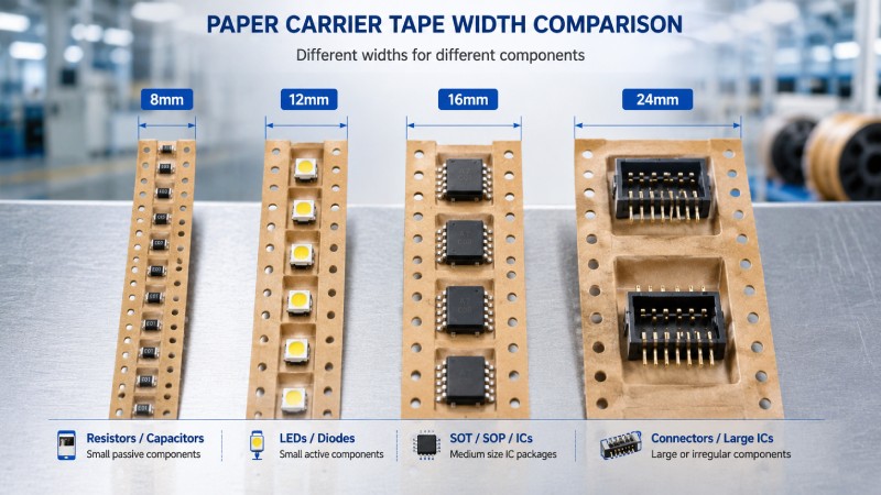
8mm Paper Carrier Tape
8mm paper tape is widely used for:
-
Chip resistors
-
Capacitors
-
Small passive components
This format offers:
-
Lower material cost
-
High reel density
-
Faster feeding performance
Because passive components dominate SMT production volume, 8mm tape remains one of the most commonly used formats in electronics manufacturing.
12mm and 16mm Tape
12mm and 16mm tape formats are commonly used for:
-
SOT packages
-
LEDs
-
Small ICs
-
Semiconductor devices
These widths provide additional pocket space while maintaining efficient reel handling.
They are often preferred when components require:
-
Better orientation control
-
Improved transportation stability
-
Larger cavity dimensions
24mm and Wider Tape
Larger tape widths are generally used for:
-
Connectors
-
Large IC packages
-
Irregular components
-
Specialized electronic assemblies
Wider tape improves component stability during transportation and reduces movement inside larger pockets.
Although material cost increases, wider tape often reduces production risk for sensitive or high-value components.
Understanding Pocket Design Dimensions
Pocket design involves much more than basic cavity sizing.
A properly designed pocket must control component movement while supporting stable automated pickup.
Component Retention Requirements
Carrier tape pockets must hold components securely throughout:
-
Packaging
-
Transportation
-
Storage
-
Automated feeding
Excessive internal movement may affect orientation consistency and pickup accuracy.
For lightweight components, even shipping vibration can cause positioning changes inside oversized pockets.
Pocket Corner Radius
Pocket corner radius affects both manufacturing quality and component protection.
Sharp corners may:
-
Damage fragile component edges
-
Increase forming stress
-
Reduce tape durability
Rounded corners generally improve:
-
Forming consistency
-
Component safety
-
Material flow during production
Pocket Bottom Design
Pocket bottom structure influences vacuum pickup performance.
Some designs use:
-
Flat bottom cavities
-
Support ribs
-
Specialized pickup zones
These features help improve nozzle contact stability during SMT placement.
For miniature electronic components, pocket bottom precision becomes extremely important.
Anti-Static Considerations
Paper carrier tape dimensions also interact with ESD protection requirements.
In some applications, dimensional design must work together with:
-
Anti-static coatings
-
Material conductivity
-
Surface resistance control
This becomes particularly important for sensitive semiconductor components.
EIA-481 Standards for Paper Carrier Tape Dimensions
Most SMT carrier tape dimensions follow EIA-481 industry standards.
These standards define dimensional requirements for:
-
Tape width
-
Pocket spacing
-
Hole positioning
-
Component orientation
-
Reel compatibility
The purpose of EIA-481 is to ensure compatibility between:
-
Carrier tapes
-
SMT feeders
-
Pick-and-place machines
-
Reel systems
Without standardized dimensions, automated assembly systems would experience major compatibility problems.
For example, if a tape supplier uses non-standard sprocket hole positioning, the tape may not feed correctly on standard SMT equipment.
Professional SMT manufacturers usually verify:
-
Dimensional tolerances
-
Feeding performance
-
Peel strength
-
Pocket alignment
before approving mass production packaging.
Buyers should always confirm whether carrier tape products comply with EIA-481 requirements, especially for export-oriented electronics manufacturing.
How to Choose the Correct Paper Carrier Tape Dimensions
Selecting proper carrier tape dimensions begins with understanding the component itself.
Start With Component Drawings
Component drawings provide essential dimensional information including:
-
Body length
-
Width
-
Height
-
Lead structure
-
Orientation requirements
Accurate drawings help engineers design proper cavity clearances and retention structures.
Consider SMT Feeding Speed
High-speed SMT lines generally require tighter dimensional tolerances.
At higher production speeds:
-
Feeding precision becomes more sensitive
-
Pickup timing becomes stricter
-
Dimensional consistency becomes more critical
Carrier tape quality that works on slower lines may fail under high-speed production conditions.
Evaluate Transportation Risks
Long-distance transportation introduces vibration, impact, and environmental stress.
For export shipments, carrier tape dimensions should provide enough retention stability to protect components throughout:
-
Warehouse handling
-
Container shipping
-
Truck transportation
-
Reel storage
Verify Feeder Compatibility
Different feeder systems may have slightly different tolerance sensitivity.
Before mass production, manufacturers should perform:
-
Sample testing
-
Pilot runs
-
Feeding validation
-
SMT compatibility checks
This process helps prevent large-scale packaging failures later.
Common Paper Carrier Tape Dimension Challenges
Small dimensional inconsistencies in paper carrier tape can affect SMT feeding stability and packaging performance. Even when the tape generally follows industry standards, variations in pocket size, pitch accuracy, or hole positioning may influence automated production efficiency.
Pocket Size Variation
If pockets are too large, components may shift during transportation. If pockets are too tight, packaging efficiency and component protection may be affected. Proper cavity clearance helps maintain stable pickup positioning.
Pocket Pitch Consistency
Pocket pitch controls feeder synchronization. Stable pitch accuracy helps improve continuous feeding performance and reduces alignment deviation during high-speed SMT production.
Sprocket Hole Position Accuracy
Sprocket holes guide the tape through SMT feeders. Consistent hole positioning supports smoother indexing and more stable automated feeding.
Cover Tape Alignment
Proper cover tape alignment helps maintain stable sealing performance and reliable component retention during reel handling and transportation.
Tape Flatness
Stable tape geometry improves reel winding consistency and supports smoother feeding performance during automated assembly.
Custom Paper Carrier Tape Dimensions for Special Components
Standard carrier tape sizes are not always suitable for specialized electronic components.
Custom dimensions are often required for:
-
Irregular shapes
-
Fragile devices
-
Miniature components
-
High-value semiconductor products
Custom carrier tape development typically includes:
-
Component evaluation
-
Pocket structure design
-
Prototype sampling
-
Feeding validation
-
Production optimization
To develop accurate custom tape solutions, buyers should provide:
-
Component drawings
-
Physical samples
-
Packaging orientation requirements
-
Reel specifications
-
SMT machine information
The more detailed the technical information, the more stable and reliable the final packaging solution becomes.
Conclusion
Paper carrier tape dimensions directly affect SMT packaging reliability, automated feeding performance, and component protection.
Although many buyers focus only on tape width, real production stability depends on a combination of factors including:
-
Pocket pitch
-
Cavity dimensions
-
Pocket depth
-
Sprocket hole accuracy
-
Cover tape alignment
Understanding these dimensions helps manufacturers reduce packaging problems, improve SMT efficiency, and avoid costly production downtime.
For specialized electronic components, custom carrier tape design and dimensional validation are often essential for achieving long-term packaging stability and automated assembly success.



 Emial
Emial John Mr


