








How to Design Paper Carrier Tape for SMT Packaging
Paper carrier tape plays a critical role in modern SMT packaging. Even small design mistakes can lead to feeding instability, component flipping, pick-and-place errors, or production downtime. For electronics manufacturers, OEM factories, and tape & reel service providers, a properly designed paper carrier tape improves packaging efficiency, protects sensitive components, and ensures stable automated assembly.
Unlike generic packaging materials, SMT carrier tape must be engineered around the exact dimensions, tolerances, and feeding behavior of electronic components. Pocket geometry, tape width, pitch spacing, and cover tape compatibility all affect how smoothly components move through high-speed pick-and-place machines.
In this guide, you will learn how to design paper carrier tape step by step, including critical technical parameters, EIA-481 considerations, common design mistakes, and practical engineering recommendations for reliable SMT packaging.
What Is Paper Carrier Tape?
Paper carrier tape is a type of SMT packaging material used to hold and transport electronic components during automated assembly processes. It is widely used for lightweight passive components such as resistors, capacitors, LEDs, and small IC packages.
The tape contains evenly spaced pockets that securely hold components in a fixed orientation. A cover tape seals the pockets during transportation and storage, while sprocket holes along the edge allow accurate indexing inside pick-and-place equipment.
Compared with embossed plastic carrier tape, paper carrier tape is often more cost-effective and environmentally friendly for smaller components and high-volume production.
How Paper Carrier Tape Works in Tape & Reel Packaging
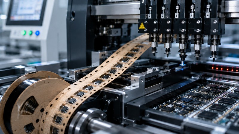
In a typical tape and reel packaging process, electronic components are loaded into paper carrier tape pockets before being sealed with cover tape. The completed tape is then wound onto reels for automated SMT feeding.
When the reel enters the pick-and-place machine, the sprocket holes synchronize with the feeder mechanism. The cover tape peels away at a controlled angle while vacuum nozzles pick components directly from the pockets.
Stable feeding depends heavily on precise tape design. Even slight inconsistencies in pocket dimensions or pitch accuracy can create alignment problems during high-speed assembly.
Common Components Packaged with Paper Carrier Tape
Paper carrier tape is commonly used for:
-
Chip resistors
-
MLCC capacitors
-
LEDs
-
Small semiconductor devices
-
Passive SMT components
-
Lightweight miniature electronic parts
Because these components are typically small and lightweight, paper carrier tape offers a practical balance between cost, feeding stability, and production efficiency.
Why Proper Paper Carrier Tape Design Matters
Many SMT packaging issues originate from improper carrier tape design rather than feeder equipment. A well-designed tape protects components while maintaining smooth automated feeding.
Preventing Component Damage
Pocket size and shape directly affect component stability during transportation. If the pocket is too large, components may rotate or collide inside the cavity. If it is too tight, edges or terminals may become damaged during loading or sealing.
Proper cavity depth also reduces vertical movement and helps prevent chipping or cracking.
Improving Pick-and-Place Stability
Pick-and-place systems rely on consistent indexing accuracy. Stable pocket spacing and sprocket hole positioning allow feeders to present components accurately at high speed.
Poor dimensional consistency can lead to:
-
Mis-picks
-
Nozzle alignment failures
-
Component flipping
-
Feeding interruptions
In high-volume SMT production, even a small increase in feeder error rates can significantly reduce manufacturing efficiency.
Reducing Packaging Costs
Optimized carrier tape design helps reduce:
-
Material waste
-
Feeding downtime
-
Scrap rates
-
Manual intervention
-
Production interruptions
Reliable packaging also lowers the risk of customer complaints and quality claims.
Key Design Parameters for Paper Carrier Tape
Designing paper carrier tape requires balancing component protection, feeder compatibility, and production efficiency.
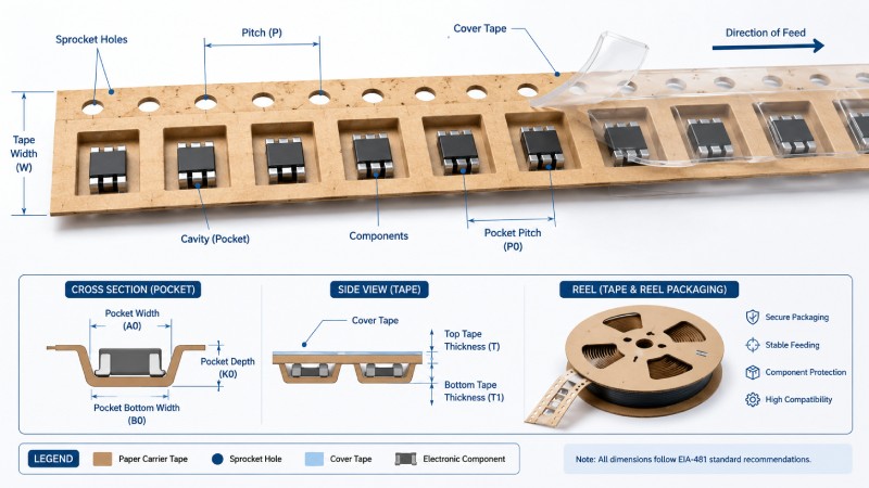
Component Dimensions and Tolerances
The first step is understanding the exact dimensions of the electronic component, including:
-
Length
-
Width
-
Height
-
Terminal structure
-
Fragile areas
Tolerance analysis is equally important. Component size variation must be considered when defining pocket clearance.
As a general principle:
-
Excessive clearance increases movement
-
Insufficient clearance causes insertion difficulty
Most carrier tape designs include controlled side clearance to stabilize the component without excessive compression.
Pocket (Cavity) Design
Pocket geometry is the core of carrier tape design.
Important considerations include:
-
Pocket depth
-
Corner radius
-
Component orientation
-
Anti-rotation features
-
Vacuum pickup accessibility
For some components, asymmetrical pocket structures help maintain orientation during feeding.
Vacuum nozzle access must also be considered carefully. The top opening should allow stable pickup without interference from pocket walls.
Tape Width Selection
Common paper carrier tape widths include:
-
8mm
-
12mm
-
16mm
-
24mm
Tape width selection depends on:
-
Component size
-
Pocket arrangement
-
Feeder compatibility
-
Production requirements
Small passive components usually use 8mm carrier tape, while larger packages may require wider formats.
Selecting unnecessarily large tape widths increases material costs and reel size without improving feeding performance.
Pitch and Pocket Spacing
Pocket pitch determines how components align with feeder indexing systems.
Incorrect pitch spacing can create synchronization problems during high-speed feeding.
Consistent pitch accuracy is especially important for:
-
High-speed SMT lines
-
Fine-pitch components
-
Precision placement applications
Designers must ensure pocket spacing follows industry-standard feeder requirements.
Sprocket Hole Design
Sprocket holes guide the tape through automated feeders.
Critical parameters include:
-
Hole diameter
-
Hole spacing
-
Hole position accuracy
-
Edge distance consistency
Improper sprocket alignment can cause:
-
Feeding jams
-
Indexing errors
-
Tape drifting
-
Position instability
Because SMT equipment relies heavily on sprocket positioning, dimensional accuracy is essential.
Cover Tape Compatibility
Paper carrier tape must work reliably with compatible cover tape materials.
The sealing system should provide:
-
Stable adhesion during shipping
-
Controlled peel strength
-
Smooth cover tape removal
-
Low component disturbance
Excessive peel force may lift components from pockets, while weak adhesion risks component loss during transportation.
Choosing the Right Paper Material for Carrier Tape
Paper material selection affects durability, static performance, sealing quality, and production stability.
Common Paper Carrier Tape Materials
Widely used materials include:
-
Kraft paper
-
Coated paper
-
Anti-static paper
-
Reinforced composite paper
Each material offers different advantages depending on the application.
For example:
-
Kraft paper is economical
-
Coated paper improves surface smoothness
-
Anti-static paper helps reduce ESD risk
Material Selection Based on Component Type
Lightweight passive components often work well with standard paper materials. Fragile or static-sensitive devices may require specialized coatings or anti-static treatment.
Environmental conditions should also be considered, including:
-
Humidity
-
Temperature
-
Transportation duration
-
Storage conditions
Proper material selection improves both packaging reliability and long-term stability.
Environmental Advantages
Compared with plastic alternatives, paper carrier tape offers several sustainability benefits:
-
Easier recycling
-
Lower plastic usage
-
Reduced packaging waste
-
Lower material costs
As electronics manufacturers focus more on sustainable packaging, paper carrier tape continues gaining popularity for suitable SMT applications.
EIA-481 Standards You Must Follow
EIA-481 is the most widely recognized standard for carrier tape and reel packaging.
The standard defines critical parameters including:
-
Tape dimensions
-
Pocket positioning
-
Sprocket hole spacing
-
Reel specifications
-
Cover tape peel force
Following EIA-481 standards ensures compatibility with global SMT assembly equipment.
Without standardized dimensions, carrier tape may not feed properly across different pick-and-place systems.
For manufacturers serving international customers, compliance with EIA standards is often mandatory.
Common Paper Carrier Tape Design Mistakes
Even experienced manufacturers occasionally encounter carrier tape design problems.
Pocket Too Large or Too Tight
Oversized pockets allow excessive component movement, increasing the risk of rotation and unstable pickup.
Undersized pockets may:
-
Damage components
-
Slow insertion speed
-
Increase loading pressure
Proper tolerance balancing is critical.
Incorrect Pocket Depth
Shallow pockets may expose components above the tape surface, increasing collision risk during sealing or transportation.
Excessively deep pockets can reduce pickup efficiency for vacuum nozzles.
Poor Cover Tape Adhesion
Improper sealing conditions may lead to:
-
Cover tape lifting
-
Inconsistent peel force
-
Component escape
-
Feeding interruptions
Seal strength testing is essential during validation.
Ignoring Automated Feeding Requirements
Some designs focus only on component fit while ignoring actual SMT feeding conditions.
Real-world testing inside production feeders is necessary to verify:
-
Indexing stability
-
Peel consistency
-
Pickup accuracy
-
High-speed feeding reliability
Step-by-Step Paper Carrier Tape Design Process
Successful carrier tape development usually follows a structured engineering process.
Step 1 — Analyze the Component
Start by collecting:
-
CAD drawings
-
Dimensional tolerances
-
Physical samples
-
Packaging requirements
Understanding the component structure is essential before pocket design begins.
Step 2 — Define Pocket Geometry
Engineers then determine:
-
Pocket dimensions
-
Clearance values
-
Orientation control
-
Feeding direction
-
Pickup window
The design should balance protection with feeder accessibility.
Step 3 — Produce Prototype Samples
Prototype carrier tape samples allow early validation before mass production.
This stage helps identify:
-
Pocket fit issues
-
Feeding instability
-
Sealing problems
-
Material concerns
Rapid prototyping shortens development time significantly.
Step 4 — Conduct SMT Feeding Tests
Real feeding tests are critical.
Testing typically includes:
-
Pick-and-place validation
-
Cover tape peel testing
-
Vibration simulation
-
Transportation testing
Design adjustments are often made after feeder trials.
Step 5 — Begin Mass Production
Once validation is complete, production moves to mass manufacturing with continuous quality monitoring.
Stable process control helps maintain:
-
Dimensional consistency
-
Pocket accuracy
-
Sealing quality
-
Reel uniformity
How to Choose a Reliable Paper Carrier Tape Manufacturer
The quality of the supplier directly affects packaging reliability.
Engineering Support Capabilities
Strong suppliers provide:
-
CAD support
-
Pocket optimization
-
Prototype assistance
-
SMT feeding analysis
Technical support is especially important for custom-shaped components.
Precision Manufacturing Equipment
Advanced production equipment improves:
-
Dimensional accuracy
-
Hole positioning consistency
-
Pocket uniformity
-
Inspection reliability
Automated vision inspection systems are increasingly important for quality control.
Experience with SMT Packaging
Manufacturers with SMT packaging experience better understand:
-
Feeder compatibility
-
EIA standards
-
Cover tape behavior
-
High-speed production requirements
Practical experience often prevents costly design mistakes.
You may also want to read:
-
“Custom Carrier Tape Design Guide”
-
“Tape and Reel Packaging Service”
Paper Carrier Tape vs Plastic Carrier Tape
Both paper and plastic carrier tape have advantages depending on the application.
| Feature | Paper Carrier Tape | Plastic Carrier Tape |
|---|---|---|
| Cost | Lower | Higher |
| Sustainability | Better | Moderate |
| Durability | Moderate | Higher |
| Best for | Small/light parts | Larger components |
| Material Flexibility | Moderate | Higher |
| Static Protection | Optional | Easier integration |
Paper carrier tape is ideal for many passive SMT components, while plastic carrier tape is often preferred for complex or heavier devices.
FAQs About Paper Carrier Tape Design
What is the standard width of paper carrier tape?
Common widths include 8mm, 12mm, 16mm, and 24mm. The correct size depends on component dimensions and feeder compatibility.
How much clearance should a carrier tape pocket have?
Clearance depends on component tolerances and feeding requirements. The goal is to minimize movement while avoiding insertion pressure.
Is paper carrier tape suitable for IC components?
Yes, some lightweight IC packages can use paper carrier tape, although larger or fragile ICs may require embossed plastic tape.
How do you test carrier tape feeding reliability?
Manufacturers typically perform pick-and-place testing, peel force testing, transportation simulation, and feeder validation before production approval.
Can paper carrier tape be customized?
Yes. Custom paper carrier tape can be designed for unique component dimensions, shapes, orientations, and SMT feeding requirements.
Conclusion
Designing paper carrier tape requires more than simply matching component dimensions. Pocket geometry, tape width, sprocket positioning, material selection, and cover tape compatibility all influence SMT feeding reliability and packaging performance.
A properly engineered paper carrier tape helps reduce feeding errors, protect sensitive components, and improve production efficiency across automated SMT lines.
For manufacturers handling custom electronic components, working with an experienced carrier tape supplier can significantly shorten development time and reduce packaging risks.
If you are developing a new SMT packaging project, consider requesting prototype samples and feeding validation before mass production begins.



 Emial
Emial John Mr


