








How Components Are Loaded into Paper Carrier Tape – Precision Tape & Reel Packaging
Introduction
Paper carrier tape plays a critical role in modern electronics manufacturing. It not only protects sensitive components but also ensures smooth feeding into automated pick-and-place machines. Proper loading of components into carrier tape is vital for minimizing defects, preventing line stoppages, and maintaining consistent production quality. In this article, we explore the complete process of loading components into paper carrier tape, common challenges manufacturers face, and best practices to ensure high reliability and accuracy.
Why Proper Component Loading Is Critical
The loading process directly impacts the performance of SMT assembly lines. Accurate placement ensures that components remain securely in their pockets and are consistently oriented for automated pick-and-place machines. Incorrectly loaded components can lead to machine errors, damaged parts, and production downtime.
Protecting Sensitive Electronic Components
Electronic components, especially ICs and polarized devices, are highly susceptible to physical damage and electrostatic discharge. Proper loading maintains lead integrity, prevents scratches or dents, and ensures safe handling during transport.
Ensuring Reliable SMT Feeding
Pick-and-place machines rely on precise component positioning. Misaligned or improperly oriented components can cause feeding errors, requiring manual intervention and slowing production. Accurate loading is crucial for consistent machine operation.
Maintaining Production Efficiency
High-quality loading reduces the risk of defects and rework. By ensuring each component is correctly placed, manufacturers maintain line speed, minimize scrap, and optimize production throughput.
Supporting Industry Packaging Standards
Compliance with EIA-481 and other tape-and-reel standards ensures compatibility with SMT machines worldwide. Standardized pocket dimensions, tape width, and spacing guarantee uniformity and reduce the risk of assembly errors.
Overview of the Paper Carrier Tape Loading Process
The process of loading components into paper carrier tape is highly structured. Key steps include:
-
Component preparation – Inspecting, sorting, and grounding components.
-
Feeding components into the loading system – Using vibratory bowls, trays, or tubes depending on component type.
-
Orientation verification – Ensuring correct polarity and direction using vision systems.
-
Placement into pockets – Precise positioning inside each carrier tape cavity.
-
Inspection – Detecting missing, damaged, or misaligned components.
-
Cover tape sealing – Securing components with adhesive tape for protection.
-
Reel winding – Rolling the loaded tape for storage or shipment.
-
Final quality control – Verifying tension, seal integrity, and component count.
Step 1 – Preparing Components Before Loading
Before any components enter the loading system, they must be carefully prepared.
Incoming Quality Inspection
Components are examined for dimensional accuracy, lead straightness, surface defects, and solderability. Any part failing these checks is removed to avoid production problems.
Component Sorting
Parts are grouped by part number, lot, and batch to ensure consistency. This prevents assembly errors and supports traceability for quality control.
Static Protection Measures
ESD-sensitive components are handled on grounded workstations with antistatic mats, wrist straps, and controlled humidity. These measures protect components from electrostatic damage during handling.
Step 2 – Feeding Components into the Loading System
Components are fed into the loading system via different mechanisms depending on their type and geometry.
Vibratory Bowl Feeders
Used for small passive components like resistors, capacitors, and diodes. These feeders orient and deliver components continuously to the loading station.
Tray Feeding Systems
Suitable for ICs, connectors, and precise components. Components are placed in trays that are automatically indexed into the loading machine.
Tube Feeding Systems
Common for through-hole components and semiconductors that require sequential delivery. Tubes provide controlled movement and orientation.
Customized Feeding Solutions
For irregular shapes or specialized components, custom feeders ensure smooth and consistent delivery without manual intervention.
Feeding accuracy is critical. Poor feeding can result in misloaded or missing components, affecting the downstream assembly process.
Step 3 – Component Orientation and Alignment
Correct orientation is essential for proper SMT placement.
Why Orientation Matters
Polarized devices, ICs, and connectors must be placed with precise alignment. Incorrect rotation or polarity can lead to assembly failures and functional defects.
Vision Inspection Systems
High-resolution cameras check rotation angles, positions, and component direction. Misaligned parts are automatically rejected or corrected.
Automated Correction Mechanisms
Servo-driven systems or mechanical adjusters rotate and reposition components as needed, ensuring consistent pocket placement.
Risks of Incorrect Orientation
Orientation errors cause pick-and-place failures, production delays, and increased scrap rates. Proper orientation verification is vital for quality and efficiency.
Step 4 – Placing Components into Paper Carrier Tape Pockets
The core of the process is precise component placement.
Pocket Structure Basics
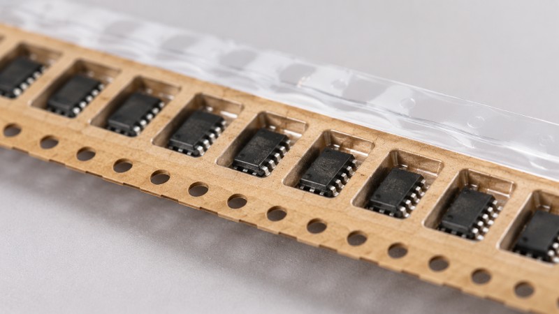
Each pocket is designed to fit specific component sizes. Width, depth, and length are standardized according to the component type to prevent movement.
Placement Accuracy Requirements
Components must be centered within pockets, maintaining consistent clearance on all sides. Misalignment can cause feeding issues during SMT assembly.
How Loading Machines Operate
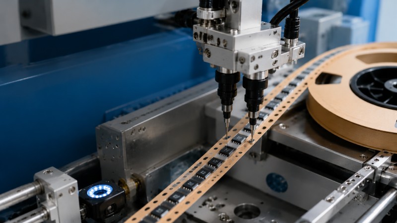
Machines use pick-and-place heads, vacuum systems, or mechanical pushers to place components accurately. The movement is synchronized with the tape indexing system.
Preventing Component Movement
Proper pocket sizing and stable placement prevent components from shifting during sealing, winding, and transport.
Step 5 – Quality Inspection During Loading
Inspection ensures each pocket contains the correct component, correctly oriented, and undamaged.
Missing Component Detection
Sensors detect empty pockets and halt the system for manual intervention.
Orientation Verification
Vision systems continuously monitor alignment, rotation, and polarity.
Pocket Occupancy Verification
Automated systems confirm that components are seated correctly within each cavity, preventing pick-and-place errors.
Automated Optical Inspection (AOI)
Real-time AOI cameras scan components on the tape. Data is used to log defects and provide feedback for process adjustments.
Step 6 – Cover Tape Sealing and Reel Winding
After loading, cover tape is applied to secure components.
Applying Cover Tape
Cover tape prevents movement, contamination, and environmental damage. It ensures safe transport and storage.
Heat Sealing Process
Machines use controlled temperature and pressure to bond the cover tape without damaging components.
Reel Winding
Loaded tape is wound onto reels under consistent tension and speed to prevent deformation or misalignment.
Final Packaging Preparation
Reels are labeled and prepared for shipment or direct feeding into SMT machines.
Common Problems During Component Loading
Even with automation, several issues can occur:
Component Tilting
Caused by pocket mismatches or improper placement. Tilted components can cause pick-and-place errors.
Missing Components
Results from feeding interruptions, jams, or machine malfunctions.
Orientation Errors
Caused by vision system failures, incorrect setup, or misalignment in the feeding mechanism.
Component Damage
Excessive force, incorrect vacuum suction, or improper handling can damage parts.
Seal Integrity Issues
Cover tape may peel or fail if sealing temperature is incorrect or tape type is mismatched.
Preventive maintenance, careful calibration, and routine inspections reduce these risks.
How Manufacturers Improve Loading Accuracy
Machine Vision Systems
Detect misaligned or damaged components before sealing.
Servo-Controlled Positioning
Ensures precise pocket placement and tape indexing.
Automated Feedback Loops
Allow continuous adjustment to compensate for mechanical tolerances or component variations.
Statistical Process Control (SPC)
Tracks process metrics, identifies trends, and prevents defects.
Continuous Quality Monitoring
Ongoing monitoring ensures high yield and reliable SMT production.
What Buyers Should Ask a Paper Carrier Tape Supplier
For high-quality tape-and-reel packaging, buyers should inquire about:
-
Loading accuracy verification and AOI inspection reports
-
Component handling capacity and batch sizes
-
Capability to handle non-standard or custom components
-
Compliance with industry standards like EIA-481
-
End-to-end tape-and-reel services, including cover tape application and reel winding
-
Quality assurance protocols and defect rate tracking
Working with a supplier that can demonstrate precision, reliability, and quality control ensures smooth downstream assembly and reduces costly errors.
Why Component Loading Quality Determines SMT Success
Component loading is more than just placing parts into pockets. Precision loading ensures smooth SMT feeding, minimizes assembly defects, and optimizes production efficiency. Reliable suppliers with advanced inspection and automated loading systems reduce manufacturing risk and support consistent electronic assembly. Choosing the right partner for tape-and-reel packaging is essential to achieving quality, efficiency, and cost-effectiveness in electronic manufacturing.



 Emial
Emial John Mr


