







Plastic Reel Flange Runout: Measurement Before Packaging
Plastic reel flange runout can be checked by mounting an empty reel on a reference spindle, positioning a dial indicator against the flange face, and rotating the reel through one complete revolution. The difference between the maximum and minimum readings gives the Total Indicator Reading (TIR) at the selected measurement position.
This inspection helps identify excessive flange wobble before carrier tape winding. However, accurate results depend on the mounting method, measurement location, and applicable acceptance criteria.
This guide explains how to measure plastic reel flange runout, distinguish axial and radial movement, record inspection results, and evaluate reel suitability before tape-and-reel packaging.
What Does Flange Runout Mean on a Plastic Reel?
Flange runout describes the variation detected at a reel flange as the reel rotates around a defined reference axis. For plastic reels used in electronic component packaging, excessive movement can indicate flange deformation, mounting eccentricity, or other dimensional problems.
The most visible symptom is often flange wobble, where the side of the reel appears to move inward and outward during rotation.
However, different types of movement require different inspection methods.
Axial Flange Runout vs. Radial Rim Runout
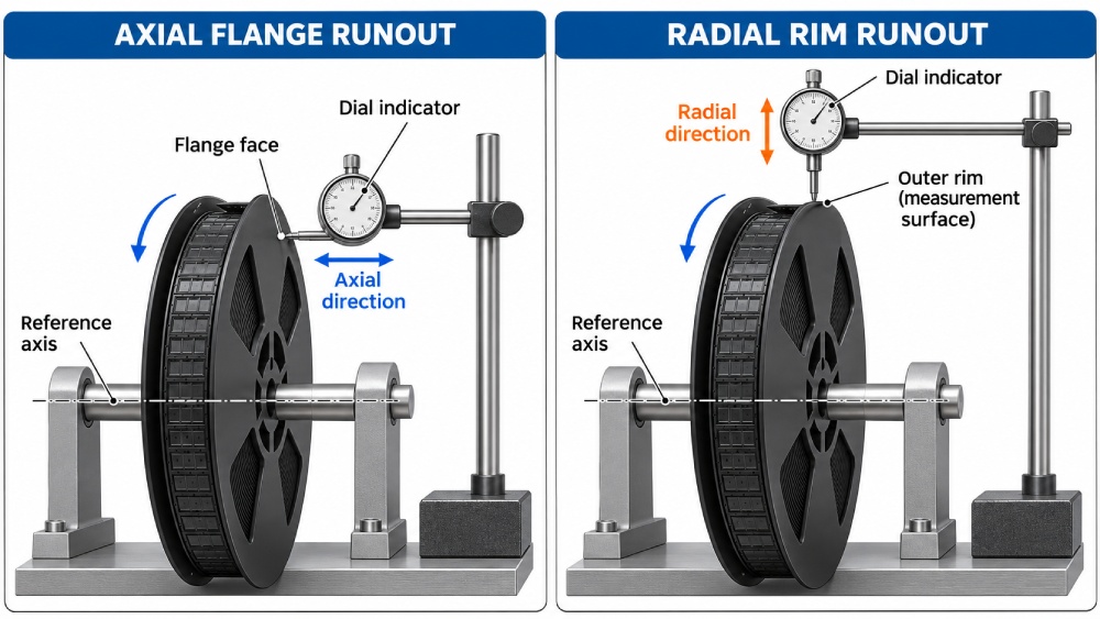
Axial and radial runout describe movement in different directions.
| Inspection Type | Measurement Direction | What It Helps Identify |
|---|---|---|
| Axial flange runout | Parallel to the reel rotation axis | Flange-face wobble and axial variation |
| Radial rim runout | Toward or away from the rotation axis | Variation in the reel‘s peripheral position |
| Hub runout | Radial to the reference axis at a suitable hub surface | Hub eccentricity or alignment problems |
| Flange width measurement | Across the flange spacing | Overall width and tape clearance |
Axial flange runout is particularly relevant when checking whether a plastic reel flange moves sideways during rotation. It is measured by placing an indicator against a specified location on the flange face.
Radial runout is measured at a suitable peripheral surface to determine how much its radial position varies during rotation.
These measurements should not be treated as interchangeable. A reel may show limited axial movement while still having an eccentric hub or irregular outer rim.
Flange Wobble vs. Static Flange Distortion
Flange wobble and flange distortion are related but different conditions.
A flange may appear warped when the reel is stationary. This can result from molding variation, uneven cooling, handling damage, or mechanical loading.
Runout, however, is evaluated while the reel rotates around a defined axis.
A stationary dimensional check can identify deformation or incorrect flange spacing, but it does not necessarily establish rotational runout.
For a broader explanation of reel dimensions and selection considerations, see Plastic Reel Specifications for Tape and Reel Packaging.
What Equipment Is Needed to Measure Plastic Reel Flange Runout?
Accurate flange runout measurement requires a stable fixture, a suitable measuring instrument, and a consistent reference axis.
The essential equipment includes:
-
Dial or Digital Indicator: Measures flange movement during rotation.
-
Reference Spindle or Arbor: Supports the reel and establishes its rotation axis.
-
Rigid Inspection Fixture: Holds the spindle securely while allowing smooth rotation.
-
Indicator Stand: Keeps the measuring probe stable and correctly positioned.
-
Approved Reel Drawing: Defines measurement locations and acceptance criteria.
Setting Up the Reel and Indicator
Mount the empty plastic reel on the reference spindle, ensuring the center hole is properly seated without excessive clearance or clamping force.
For axial flange runout measurement, position the indicator probe against a smooth flange-face area, with its measuring direction parallel to the spindle axis. Avoid reinforcing ribs, raised markings, and damaged surfaces.
Secure the indicator stand, apply light and consistent probe contact, and confirm that the reel rotates freely.
Before starting, verify that the fixture is stable, the indicator is calibrated, and the measurement position matches the approved inspection requirements.
How to Measure Plastic Reel Axial Flange Runout Step by Step
The following procedure describes a practical empty-reel inspection method. The exact fixture, contact radius, and acceptance limit should be defined in the applicable inspection instruction.
Step 1: Mount the Empty Reel on the Reference Fixture
Begin by confirming the reel model and matching it to the correct drawing or inspection specification.
Visually examine the reel for cracks, deformation, damaged center holes, or foreign material.
Place the empty plastic reel onto the reference spindle and ensure that it is seated correctly.
The reel should rotate around the designated axis without excessive play.
Before positioning the indicator, rotate the reel manually to check for obvious mounting problems or interference.
If the reel does not rotate consistently, correct the fixture or mounting condition before proceeding.
Step 2: Position and Zero the Dial Indicator
Secure the indicator to a rigid stand that remains stationary while the reel rotates.
Place the probe against the designated flange face at the specified radial measurement position.
For axial runout measurement, align the probe‘s measuring direction parallel to the reel axis.
Apply suitable preload to maintain contact without bending the flange.
Set the indicator to zero at the initial position. If using a digital indicator with maximum/minimum recording capability, reset the measurement function according to the instrument instructions.
Confirm that the probe can follow the expected flange movement throughout the rotation.
The measurement location must remain consistent for comparable readings.
Step 3: Rotate the Reel and Record the Readings
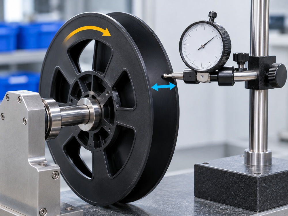
Rotate the reel slowly through one complete revolution.
Observe the indicator as the flange passes beneath the probe.
Record:
-
Maximum indicator reading.
-
Minimum indicator reading.
-
Flange side being measured.
-
Measurement position.
-
Relevant fixture or setup information.
The indicator may move in both positive and negative directions relative to the initial zero position.
Do not reset the indicator during the measurement cycle.
The difference between the maximum and minimum readings represents the TIR for the selected circular measurement path.
If the reading changes unexpectedly, inspect the probe contact and mounting condition before accepting the result.
Step 4: Calculate the Total Indicator Reading (TIR)
Calculate the runout reading using:
TIR = Maximum Indicator Reading − Minimum Indicator Reading
Use the same measurement unit for both readings.
For example, when the indicator passes through positive and negative values, subtracting the minimum signed reading from the maximum gives the full peak-to-peak movement.
A digital indicator with a suitable MAX/MIN or TIR function may perform this calculation automatically.
It is important to distinguish this measured TIR from a formal geometric total-runout requirement.
A single indicator track at a fixed radius measures variation along that circular path. It does not, by itself, establish compliance with a total-runout tolerance applied to an entire flange surface.
If the engineering drawing specifies total runout under a geometrical tolerancing system, the inspection must evaluate the required controlled surface according to that specification.
Step 5: Measure the Opposite Flange
Where both reel flanges require inspection, repeat the measurement on the opposite flange.
Maintain the same defined reference axis and equivalent measurement position whenever the approved fixture permits.
Depending on reel design, this may require repositioning the indicator, accessing the opposite side of the fixture, or using an approved alternative mounting arrangement.
If remounting the reel is necessary, verify that the mounting remains repeatable.
Record each flange separately.
One flange may show greater axial variation than the other, especially if local deformation or assembly variation is present.
Do not average the two readings unless the inspection specification explicitly requires it.
Step 6: Verify Measurement Repeatability
After the initial measurement, repeat the rotation without changing the setup.
Compare the observed maximum and minimum readings.
If results vary significantly, investigate possible sources of measurement error.
Check whether:
-
The reel has shifted on the arbor.
-
The indicator stand has moved.
-
The probe is contacting an irregular surface.
-
The spindle has excessive play.
-
Contact force is deforming the flange.
-
The reel has not seated consistently.
If necessary, remove and reinstall the reel to evaluate mounting repeatability using an approved procedure.
A stable, repeatable measurement is necessary before deciding whether the reel meets its specified runout requirement.
When Should Radial Rim Runout or Hub Runout Also Be Checked?
Axial flange runout is not the only possible cause of rotational instability.
A reel may have relatively stable flange faces but still rotate eccentrically because of its hub, center hole, or peripheral geometry.
Additional measurements can help identify these conditions.
Measuring Radial Runout at the Reel Rim
To inspect radial rim runout, position the indicator against a suitable continuous peripheral surface.
The probe should measure displacement toward or away from the reference rotation axis.
Rotate the reel manually and record the maximum and minimum readings.
Calculate the TIR using the same peak-to-peak method.
The measurement should be performed only where the rim geometry provides a suitable, uninterrupted contact track. Decorative cutouts, molding features, or discontinuous edges may prevent a meaningful indicator reading.
Record radial results separately from axial flange measurements.
Checking Hub or Center-Hole-Related Errors
If a reel shows inconsistent movement, inspect the hub and center-hole mounting condition.
Possible issues include:
-
Excessive clearance between the center hole and arbor.
-
Incorrect or inconsistent hub seating.
-
Damaged mounting surfaces.
-
Eccentric hub geometry.
-
Misalignment within an assembled reel.
A change in runout after remounting may indicate a datum or fixture problem rather than a defective flange.
When hub eccentricity is suspected, measure an appropriate hub surface using the datum specified on the drawing.
A flange-face measurement alone cannot establish whether the hub is concentric with the intended rotation axis.
How to Calculate, Record, and Interpret Reel Runout Results
A flange runout measurement is useful only when the result can be traced to a specific reel, location, and measurement setup.
Recording a TIR value without identifying the reference axis or indicator position makes later comparison difficult.
For quality inspection, the record should contain enough information for another technician to reproduce the measurement.
What to Include in a Runout Inspection Record
A practical inspection record can use the following format:
| Inspection Field | Information to Record |
|---|---|
| Reel identification | Model or part number |
| Production identification | Batch or lot number |
| Drawing reference | Drawing number and revision |
| Reference axis | Approved datum and mounting method |
| Measuring equipment | Indicator and fixture identification |
| Measurement position | Flange side and contact radius |
| Maximum reading | Actual observed value |
| Minimum reading | Actual observed value |
| Calculated TIR | Maximum minus minimum |
| Acceptance criterion | Approved specification limit |
| Inspection disposition | Release, hold, or reject |
| Traceability | Inspector and inspection date |
For reels inspected repeatedly during production, consistent records help distinguish isolated defects from recurring dimensional variation.
Common Sources of False Runout Readings
Measurement errors should be investigated before assigning a defect to the reel.
Common causes include loose fixture components, unsuitable arbor fit, probe misalignment, insufficient instrument travel, and inconsistent contact pressure.
Flexible plastic flanges deserve particular attention.
If the indicator applies excessive force, it may locally deform the surface being measured. The recorded movement can then include measurement-induced deflection.
A stable indicator stand, suitable contact force, and repeatable reel mounting are therefore essential.
If the inspection result changes after remounting, verify the setup before concluding that the part itself is inconsistent.
How to Determine Whether a Plastic Reel Is Acceptable Before Packaging
The purpose of runout inspection is not simply to produce a measurement. It is to determine whether the reel is suitable for the next packaging operation.
That decision requires a defined acceptance criterion.
Compare Results With the Approved Reel Drawing
The measured runout should be compared with the applicable controlled engineering drawing, customer specification, or approved internal inspection requirement.
There is no single flange-runout value that should be applied automatically to every plastic reel design.
Acceptability can depend on:
-
Reel diameter and flange geometry.
-
Hub and center-hole design.
-
Material stiffness and structural support.
-
Carrier tape width and intended winding configuration.
-
Packaging equipment requirements.
-
Customer-specific dimensional and functional criteria.
EIA-481-F provides requirements relevant to taping surface-mount components for automatic handling. However, it should not be cited as the source of a universal plastic reel flange-runout tolerance without verifying the specific applicable provision.
ISO 1101:2017 addresses geometric tolerancing notation and interpretation. It does not independently establish a product-specific acceptance limit for every plastic reel.
The controlling drawing or inspection specification must identify the required measurement and permissible variation.
Check Packaging and SMT Feeder Compatibility
Excessive flange movement may affect the way carrier tape is wound, stored, or unwound.
Potential problems include:
-
Intermittent contact between the tape pack and the reel flange.
-
Variation in available side clearance during winding.
-
Unstable reel rotation in packaging equipment.
-
Increased friction during unwinding.
-
Interference with reel holders or feeder components.
These effects depend on the complete packaging system. A runout reading alone does not prove that a feeder failure will occur.
For example, a wider carrier tape or a reel with limited side clearance may be more sensitive to flange movement in a particular winding arrangement.
Where the functional consequence is uncertain, an approved winding or unwinding trial may be necessary.
The relationship between reel compatibility and the wider packaging process is discussed in Tape and Reel Packaging Process Explained.
Release, Hold, or Reject the Reel
Inspection results should lead to a documented quality decision.
| Inspection Result | Recommended Action |
|---|---|
| Valid measurement meets all applicable requirements | Release for the next packaging operation |
| Measurement is unstable or cannot be reproduced | Hold and verify the inspection setup |
| Applicable acceptance criteria are unavailable | Hold for engineering clarification |
| Confirmed measurement exceeds the approved limit | Segregate and process under the nonconformance procedure |
| Dimensional result is acceptable but functional compatibility remains uncertain | Conduct the specified functional verification before release |
A reel should not be released solely because the operator cannot see any wobble.
Likewise, visible movement does not automatically establish nonconformance without considering the applicable specification and measurement method.
What Causes Excessive Plastic Reel Flange Wobble?
Excessive flange wobble can originate during manufacturing, assembly, handling, or inspection.
A systematic investigation should distinguish permanent reel defects from temporary deformation and measurement setup errors.
Manufacturing and Structural Factors
Plastic reel manufacturing processes can influence flange geometry.
Potential contributors include:
Uneven molding shrinkage: Nonuniform cooling or material shrinkage can produce distortion after molding.
Flange thickness variation: Local differences in thickness or reinforcing geometry may affect stiffness and deformation behavior.
Tooling variation: Wear, alignment problems, or dimensional variation in tooling may affect finished reel geometry.
Hub-to-flange alignment: For assembled reel designs, inconsistent positioning or attachment of the flange relative to the hub may introduce rotational variation.
Material and structural behavior: Different polymer formulations and flange designs can respond differently to manufacturing conditions, temperature, and applied force.
A recurring runout issue should be investigated using actual inspection records, approved drawings, and relevant process information rather than assuming a particular material is defective.
Handling and Fixture-Related Factors
A correctly manufactured reel can also become distorted after production.
Possible causes include excessive stacking pressure, unsuitable packaging support, transport damage, and mechanical stress during handling.
Temperature exposure may contribute to dimensional changes depending on the material and loading conditions.
Measurement setup problems can produce similar symptoms.
For example, a reel mounted at an angle may appear to wobble even when the flange geometry is otherwise acceptable relative to its intended datum.
Troubleshooting Excessive Reel Runout
| Observed Problem | Possible Cause | Recommended Check |
|---|---|---|
| Reading changes after remounting | Arbor clearance or inconsistent seating | Verify fixture fit and mounting datum |
| Sudden indicator movement at one location | Surface damage or irregular molding feature | Inspect the contact track |
| One flange shows greater movement | Local deformation or assembly variation | Inspect both flange faces |
| Reading changes with probe pressure | Flexible flange deflection | Check indicator contact force |
| Similar problems occur across multiple reels | Possible tooling or process variation | Review lot records and process conditions |
| Reel wobbles on packaging equipment but not on the inspection fixture | Equipment mounting or compatibility issue | Check reel holder and spindle interface |
When investigating a suspected batch problem, inspect appropriate samples under the same controlled conditions.
If the results consistently indicate a manufacturing-related issue, the findings should be reviewed with the responsible production or tooling engineers.
Do not attempt to correct a nonconforming reel by manually bending the flange unless an approved rework method exists.
Pre-Packaging Plastic Reel Inspection Checklist
Before an empty reel proceeds to carrier tape winding, operators can use the following checklist.
-
Confirm the correct reel model and drawing revision.
-
Check the center hole, hub, and flange surfaces for visible damage.
-
Verify the reference arbor and inspection fixture.
-
Confirm the indicator is suitable and within calibration.
-
Position the probe at the approved measurement location.
-
Measure and record the required flange-face runout.
-
Perform radial or hub checks when specified.
-
Verify repeatability if readings are inconsistent.
-
Compare results with the approved acceptance criteria.
-
Document the inspection result and disposition.
This checklist supports routine quality control but does not replace a model-specific inspection instruction.
For production inspection, the approved procedure should also define the required sampling frequency and any additional functional checks.
Frequently Asked Questions
Can a plastic reel pass a flange-width inspection but still have excessive wobble?
Yes. Flange width and axial flange runout evaluate different characteristics. A reel may meet its static width requirement but show excessive movement when rotated around its reference axis. Where both characteristics are specified, they should be checked independently.
Why do runout readings change when the same reel is mounted on another arbor?
Different arbor fits, seating conditions, or alignment errors can change the effective rotation axis. These changes may affect the indicator reading. Verify the datum, fixture condition, and mounting repeatability before comparing results obtained on different setups.
Does EIA-481 specify one universal flange-runout tolerance for all plastic reels?
A universal numerical tolerance should not be assumed from EIA-481. The applicable standard provisions, reel drawing, and customer requirements must be reviewed. Product-specific acceptance limits should be taken from the controlling technical documentation.
Should plastic reel runout be checked before winding or after packaging?
Checking an empty reel before winding helps identify reel-related defects before carrier tape and electronic components are loaded. Additional inspection after winding may be appropriate when packaging stability, flange clearance, or unwinding performance requires verification.
Final Inspection Considerations
Plastic reel flange runout inspection should be performed using a stable reference fixture, a suitable indicator, and a clearly defined measurement position.
The most important steps are establishing the correct rotation axis, obtaining repeatable maximum and minimum readings, calculating TIR, and comparing the result with the approved specification.
When abnormal movement is detected, fixture errors and mounting conditions should be ruled out before identifying the reel as defective.
For new reel designs, sample approval, or recurring packaging issues, the reel drawing, inspection setup, and measured results should be reviewed together.
If a packaging application requires a different reel geometry or improved clearance, the available plastic reel products can be considered alongside the carrier tape dimensions and equipment requirements.
A repeatable inspection method helps quality and packaging teams identify reel-related problems before they affect carrier tape winding or downstream SMT feeding.



 Emial
 John Mr